
Wireless communication system, base station and mobile station

a wireless communication and base station technology, applied in the direction of wireless commuication services, electrical equipment, transmission path sub-channel allocation, etc., can solve the problems of reducing the throughput of neighboring cells, reducing the throughput of cell-edge mss, and sometimes not being able to accommodate cell-edge mss in the cell-edge band, so as to prevent an increase in interference power and increase the utilization efficiency of wireless resources

Inactive Publication Date: 2010-12-09
HITACHI LTD
View PDF5 Cites 27 Cited by
  • Summary
  • Abstract
  • Description
  • Claims
  • Application Information

AI Technical Summary

Benefits of technology

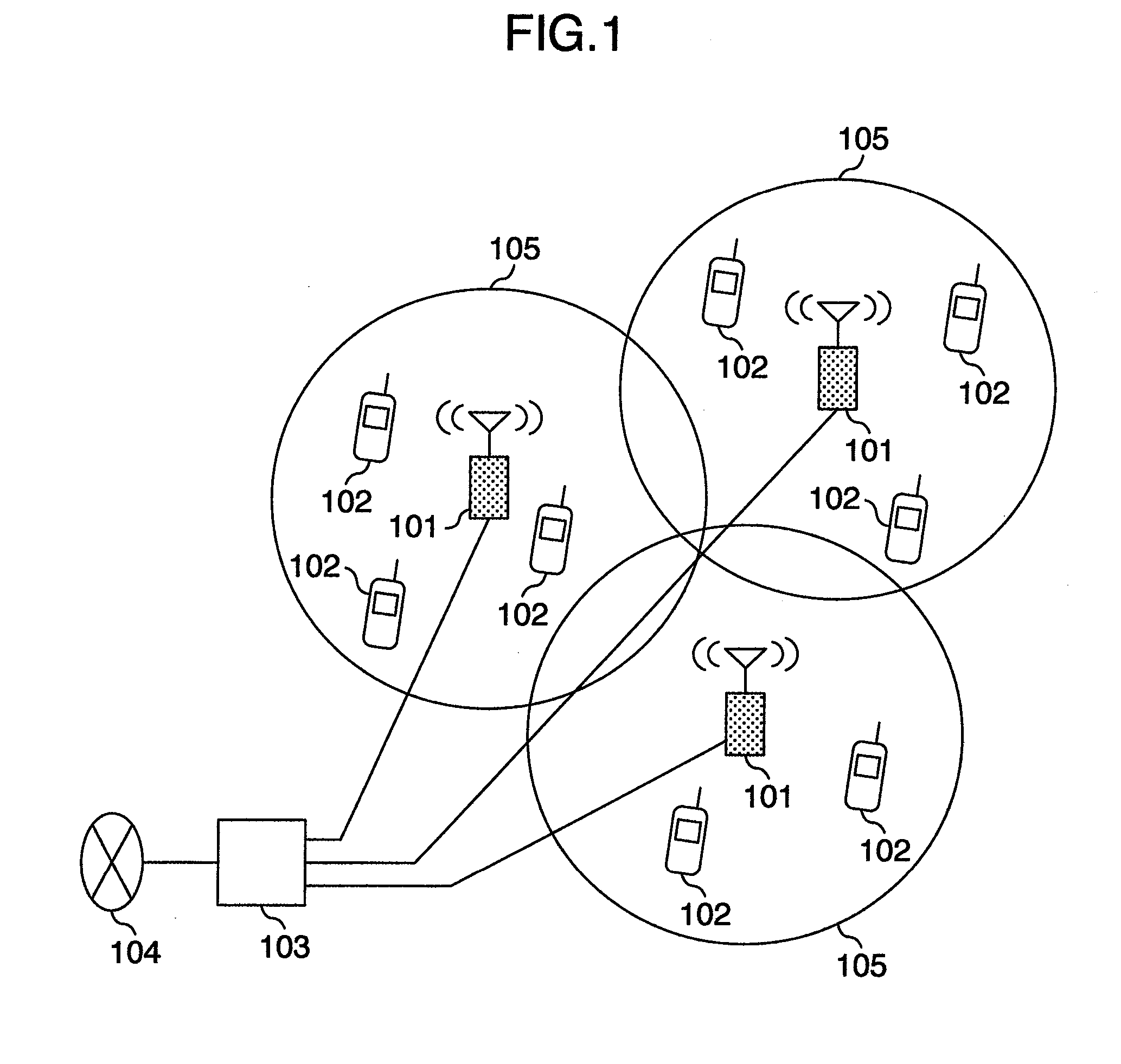
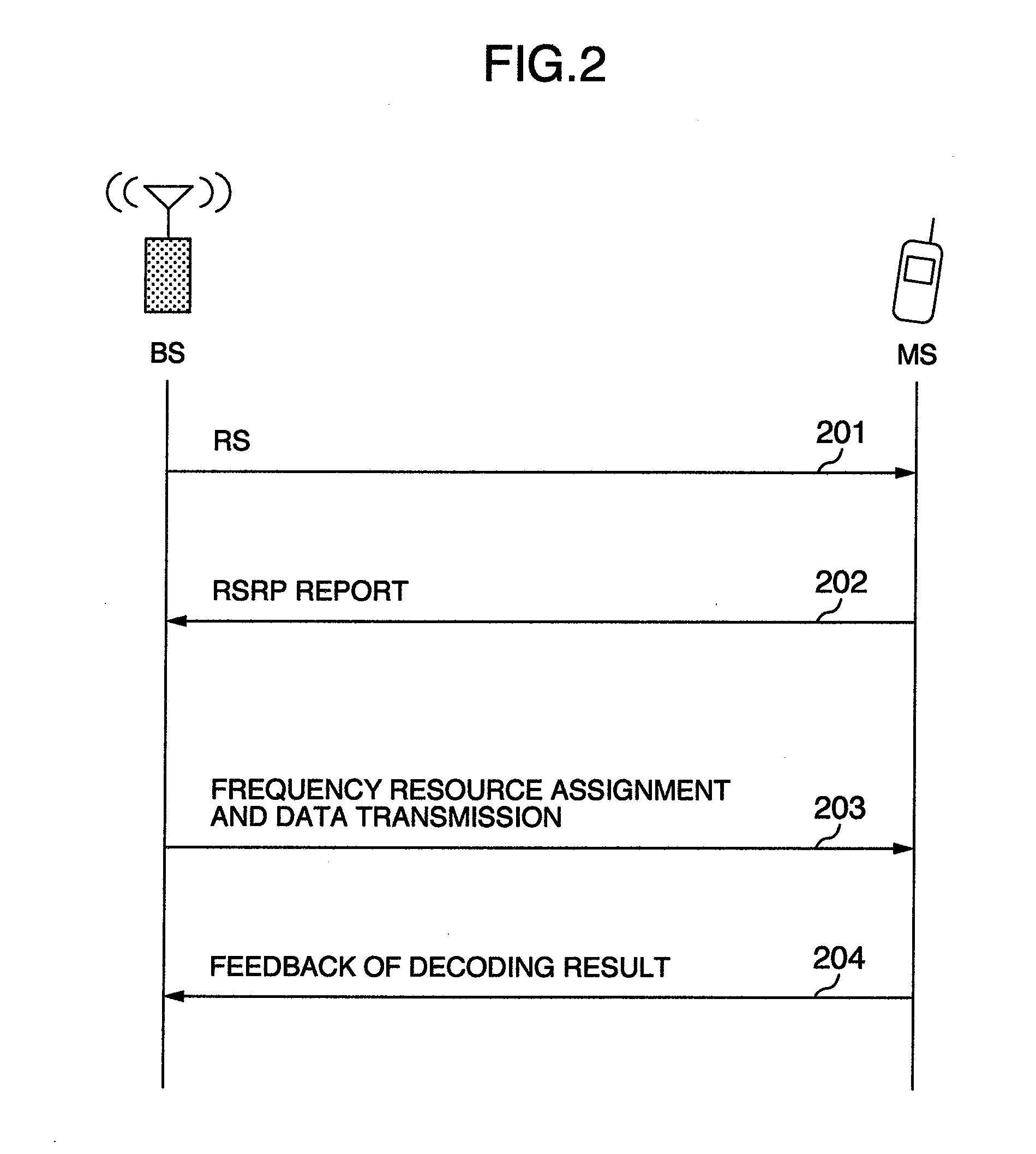
[0011]A BS can reduce the received interference power of an MS by assigning frequency resources, where the transmit power of the neighboring BSs is low, to a cell-edge MS that is more likely affected by interference and by assigning frequency resources, where the transmit power of the neighboring BSs is high, to a cell-center MS that is less likely affected by interference. In addition, when subcarriers to be assigned to a cell-edge MS of a BS are decided, the BS can use the information notified by HII to select subcarriers, not yet assigned to a cell-edge MS in the neighboring BSs, to reduce interference between the cell-edge MSs.
[0013]As the amount of cell-edge band is increased when the system bandwidth is partitioned into the cell-edge band and the cell-center band, the limitation on the transmit power is reduced and, as a result, the throughput of the cell is expected to increase. An increase in the amount of cell-edge band, however, increases interference to the neighboring cells, sometimes resulting in a decrease in the throughput of the neighboring cells.
[0017]The present invention prevents an increase in interference power to the neighboring cells to allow for inter-cell interference control for ensuring equal connectivity among cells, thus increasing the usage efficiency of wireless resources.

Problems solved by technology

An increase in the amount of cell-edge band, however, increases interference to the neighboring cells, sometimes resulting in a decrease in the throughput of the neighboring cells.
Another problem is that, as the number of cell-edge MSs is increased when the connected MSs in each cell are classified into cell-edge MSs and cell-center MSs, the cell-edge band sometimes cannot accommodate cell-edge MSs.
This results in a decrease in the throughput of the cell-edge MSs.

Method used


Image

  • Wireless communication system, base station and mobile station
  • Wireless communication system, base station and mobile station
  • Wireless communication system, base station and mobile station

Examples


first example

[0085]A first example of the present invention will be described below with reference to FIG. 13. In the first example, an unnecessary increase in the amount of cell-edge band is prohibited on the downlink based on the information obtained from the neighboring cells.

[0086]FIG. 13 is a flowchart showing an example of the procedure for use by a BS, which performs bandwidth partitioning, to determine if a change from a cell-center band to a cell-edge band is to be prohibited based on the information obtained from the neighboring cells. In the example shown in FIG. 13, the information obtained from the neighboring cells is RNTP. Referring to FIG. 13, the BS first calculates the statistical amount of RNTP information obtained from the neighboring cells (1301). The statistical amount of RNTP information is, for example, the total of RNTP from the neighboring cells calculated by adding up in the frequency direction or the amount of RNTP accumulated for a predetermined period. If the RNTP s...

second example

[0088]A second example of the present invention will be described below with reference to FIG. 14. In the second example, an unnecessary increase in the amount of cell-edge band is prohibited on the uplink based on the information obtained from the neighboring cells.

[0089]FIG. 14 is a flowchart showing an example of the procedure for use by a BS, which performs bandwidth partitioning, to determine if a change from a cell-center band to a cell-edge band is to be prohibited based on the information obtained from the neighboring cells. In the example shown in FIG. 14, the information obtained from the neighboring cells is HII. Referring to FIG. 14, the BS first calculates the statistical amount of HII information obtained from the neighboring cells (1401). The statistical amount of HII information is, for example, the total of HII from the neighboring cells calculated by adding up in the frequency direction or the amount of HII accumulated for a predetermined period. If the HII statist...

third example

[0091]A third example of the present invention will be described below with reference to FIG. 15. In the third example, an unnecessary increase in the amount of cell-edge band is prohibited according to whether or not the cell-edge band can accommodate the MSs. The third example may be applied to both the downlink and the uplink.

[0092]FIG. 15 is a flowchart showing an example of the procedure for use by a BS to determine if a change from a cell-center band to a cell-edge band is to be prohibited according to whether the cell-edge band can accommodate the MSs. In FIG. 15, after the frequency resource assignment, the BS first checks if the cell-edge band can accommodate all MSs (1501). Whether or not the cell-edge band can accommodate all MSs may be determined, for example, based on the result in a predetermined period in the past. If the cell-edge band can accommodate all MSs (Yes in 1501), the BS determines that there is no need to increase the amount of cell-edge band and prohibits...


PUM


Abstract

In a system of the present invention, the amount of cell-edge band is limited. In addition, the upper limit of the amount of cell-edge band in each cell is set for limiting the amount of cell-edge band based on the upper limit. The number of cell-edge MSs is also limited. In addition, the upper limit of the number of cell-edge MSs in each cell is set for limiting the number of cell-edge MSs based on the upper limit.

Description

INCORPORATION BY REFERENCE[0001]The present application claims priority from Japanese application JP 2009-135688 filed on Jun. 5, 2009, the content of which is hereby incorporated by reference into this application.BACKGROUND OF THE INVENTION[0002]The present invention relates to a wireless communication system, for example, to a wireless communication system, a base station (BS), and a mobile station (MS) that use an OFDMA (Orthogonal Frequency Division Multiple Access) based communication method for implementing cellular communication.[0003]OFDMA is employed in many cases as the user multiplexing method in wireless communication. In OFDMA, many subcarriers provided by the OFDM (Orthogonal Frequency Division Multiplexing) method are assigned to MSs, some subcarriers to each MS, as the frequency resources for realizing simultaneous access by multiple MSs. In the OFDMA method, the frequency resources used for data communication must be assigned before data is transmitted. For example...

Claims


Application Information

Patent Timeline
IPC IPC(8): H04W40/00
CPCH04L5/003
Inventor KATAYAMA, RINTAROTAMAKI, SATOSHIYAMAMOTO, TOMONORIISHII, HIROTAKE
Owner HITACHI LTD
Learn More