Electrode group for secondary battery and secondary battery using the same

a secondary battery and electrode group technology, applied in the direction of wound/folded electrode electrodes, cell components, sustainable manufacturing/processing, etc., can solve the problems of internal short circuit between the positive electrode and the negative electrode, rapid temperature rise in the battery, and fractured electrode plates, etc., to achieve high reliability and safety, reduce fracture or buckling of electrode plates

Inactive Publication Date: 2010-12-09
PANASONIC CORP
View PDF6 Cites 32 Cited by
  • Summary
  • Abstract
  • Description
  • Claims
  • Application Information

AI Technical Summary

Benefits of technology

[0021]According to the present invention, stress applied at the time of configuring an electrode group, or stress caused due to expansion/contraction at the time of charge/discharge of elect

Problems solved by technology

However, along with increase in capacity, rapid temperature rise may occur in a battery when an internal short circuit is occurred between a positive electrode and a negative electrode.
Moreover, when the electrode plates expand/contract along with charge/discharge of the battery, at least one of the electrode plates may be buckled due to stress applied thereto, so that the electrode plate may be fractured.
When the electrode plate i

Method used


Image

  • Electrode group for secondary battery and secondary battery using the same
  • Electrode group for secondary battery and secondary battery using the same
  • Electrode group for secondary battery and secondary battery using the same

Examples


first embodiment

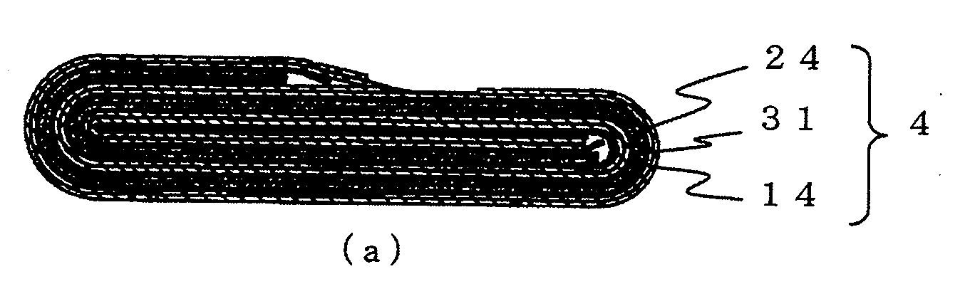
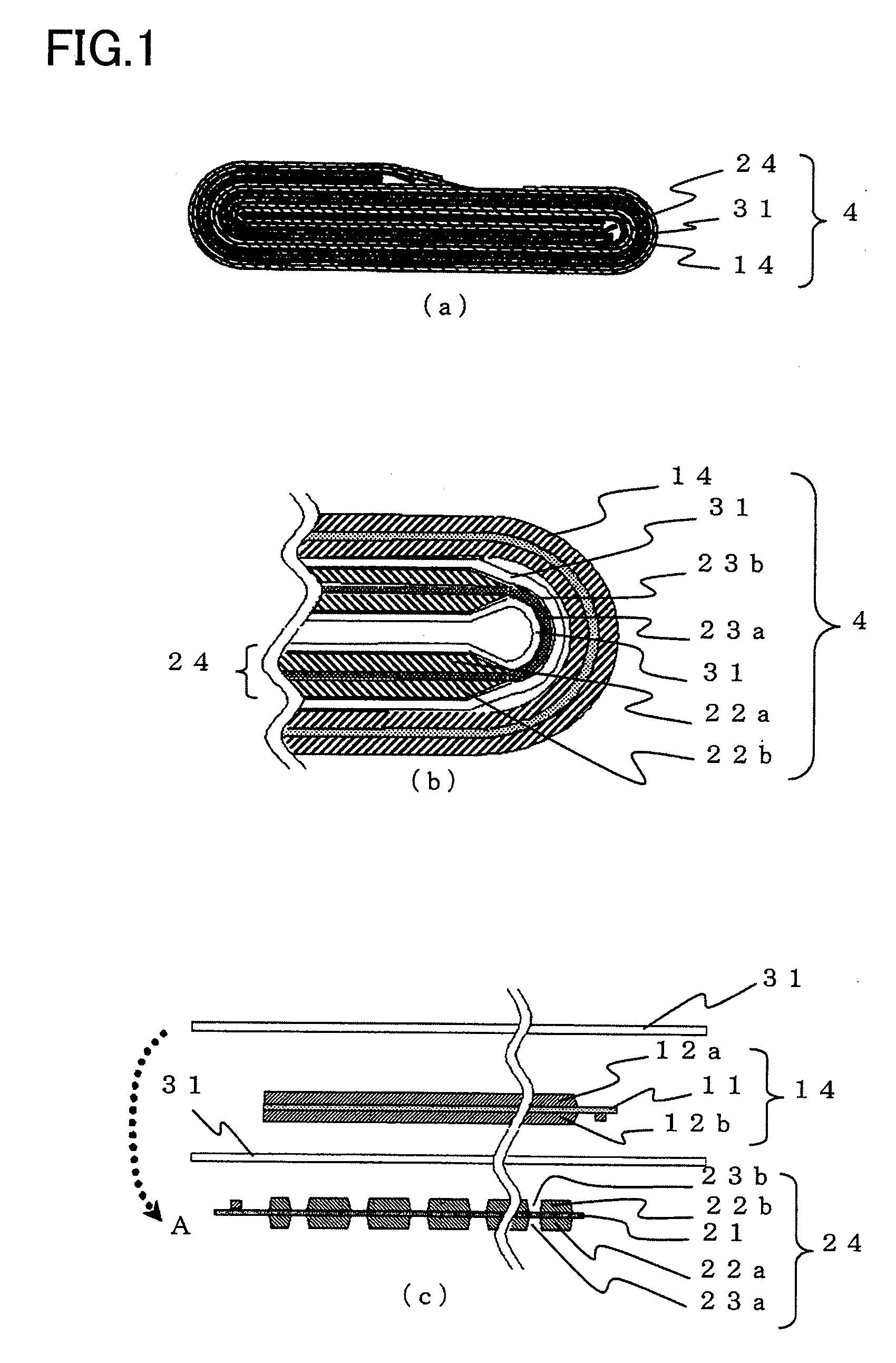
[0040]FIG. 1A is a cross-sectional view schematically illustrating a configuration of a secondary battery electrode group of a first embodiment of the present invention. FIG. 1B is a partially enlarged cross-sectional view illustrating a curved portion and its neighborhood located at an end portion in a major axis direction of the electrode group formed into a flat shape. FIG. 1C is a cross-sectional view illustrating a configuration of a positive electrode, a negative electrode, and a separator before forming the electrode group.

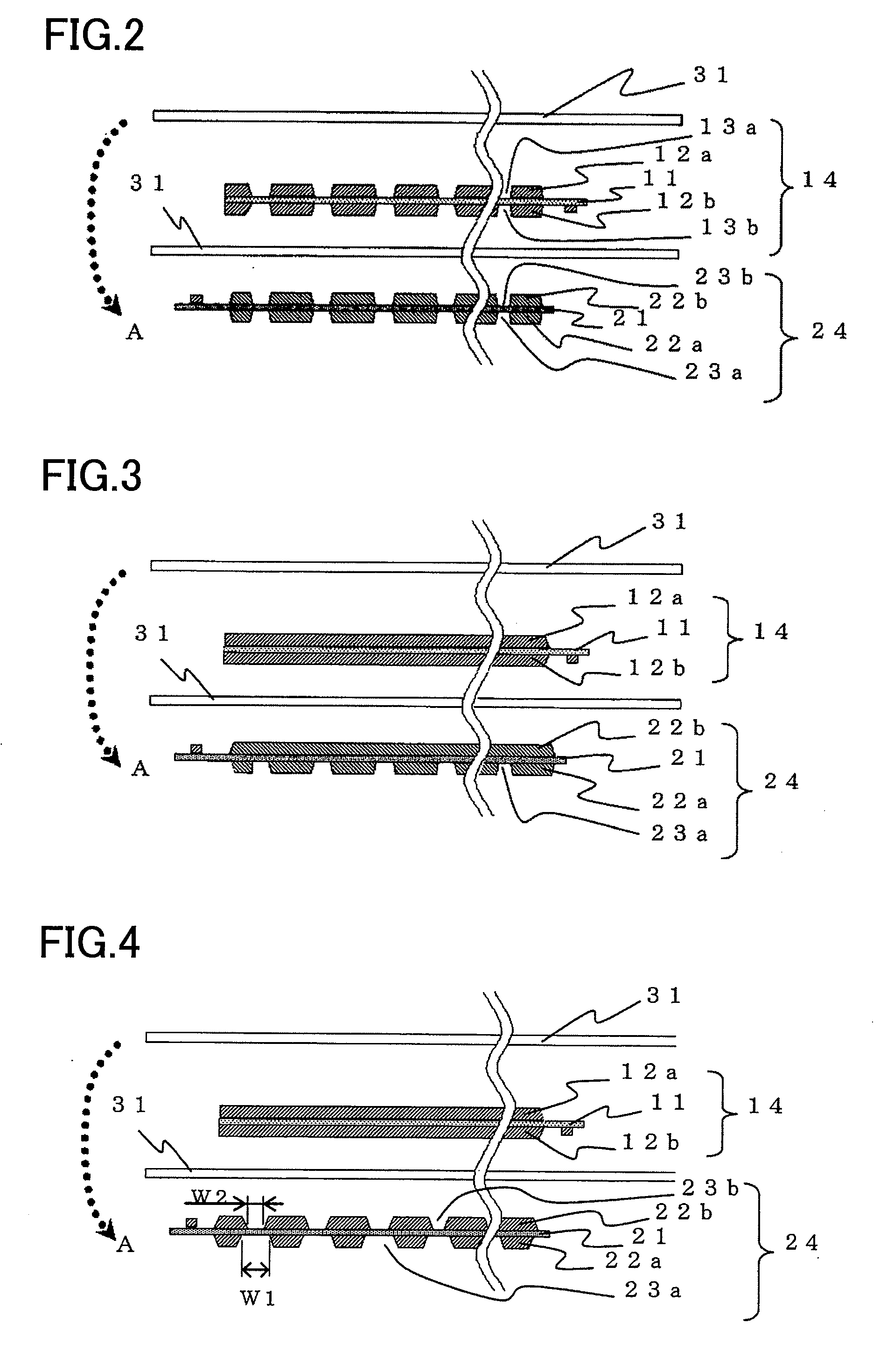
[0041]As illustrated in FIGS. 1A-1C, a positive electrode 14 having a positive electrode current collector 11 on which positive electrode mixture layers 12a, 12b are formed and a negative electrode 24 having a negative electrode current collector 21 on which negative electrode mixture layers 22a, 22b are formed are wound with a separator 31 interposed therebetween to form an electrode group 4 having a flat shape. In the curved portion located at the end por...

second embodiment

[0058]In the first embodiment, the uncoated portion where the mixture layer is not formed on the current collector is provided in the curved portion located at the end portion in the major axis direction of the flat electrode group to alleviate stress applied at the time of configuring the electrode group, or stress caused due to expansion / contraction of the electrode plates at the time of charge / discharge so that the advantage of reducing, for example, fracture of the electrode plate is obtained. Since a cylindrical electrode group also has a portion having a small radius of curvature at the start end of the winding of the electrode group, a similar advantage can be obtained by providing the relevant portion with an uncoated portion where a mixture layer is not formed.

[0059]FIG. 9A is a cross-sectional view schematically illustrating a configuration of a secondary battery electrode group of a second embodiment of the present invention. FIG. 9B is a partially enlarged cross-sectiona...

examples

[0073]The present invention will be described in detail below with reference to examples.


PUM


Abstract

A positive electrode 14 has a positive electrode current collector 11 on which positive electrode mixture layers 12a, 12b are formed. A negative electrode 24 has a negative electrode current collector 21 on which negative electrode mixture layers 22a, 22b are formed.
The positive electrode 14 and the negative electrode 24 are wound into a flat shape with a separator 31 interposed therebetween, thereby an electrode group 4. In a curved portion located at an end portion in a major axis direction of the electrode group 4, at least one of the positive electrode 14 or the negative electrode 24 is provided with uncoated portions 13a, 13b; 23a, 23b in which the mixture layers 12a, 12b; 22a, 22b are not formed on the current collector 11;21.

Description

TECHNICAL FIELD[0001]The present invention relates to electrode groups used for nonaqueous secondary batteries represented by lithium ion batteries, and to nonaqueous secondary batteries using the same.BACKGROUND ART[0002]In recent years, lithium ion secondary batteries have been widely used as power supplies for mobile electronic devices. In such a lithium secondary battery, as active materials, for example, a carbon material capable of inserting and extracting lithium is used for a negative electrode, and a composite oxide containing transition metal and lithium, such as LiCoO2, is used for a positive electrode, thereby providing a nonaqueous secondary battery having high potential and high discharge capacity. However, with the development of electronic devices and communication devices having an increased range of functions, a smaller size, and a reduced thickness in recent years, lithium ion secondary batteries having an increased capacity are required.[0003]However, along with ...

Claims


Application Information

Patent Timeline
IPC IPC(8): H01M2/18H01M2/02H01M4/13H01M10/04H01M10/0566H01M10/0583H01M10/0587
CPCH01M4/13H01M10/0431Y02E60/122H01M10/0583H01M10/0587H01M10/052Y02E60/10Y02P70/50H01M2004/021
Inventor KANEDA, MAYUMISUETSUGU, DAISUKEKATO, SEIICHI
Owner PANASONIC CORP
Why Eureka
Try Eureka