Air filter

a technology of air filter and filter body, which is applied in the direction of ventilation system, electrical apparatus casing/cabinet/drawer, separation process, etc., can solve the problems of requiring maintenance, consuming energy for cooling equipment, and typically leaving equipment unattended for extended periods

Inactive Publication Date: 2010-12-09
4ENERGY LTD
View PDF16 Cites 17 Cited by
  • Summary
  • Abstract
  • Description
  • Claims
  • Application Information

AI Technical Summary

Benefits of technology

[0014]The air filter preferably has an inlet area that is substantially larger than the outlet area, so that air is drawn in through the inlet passageway and p...

Problems solved by technology

In applications where electrical equipment is to be used in remote locations, for example in mobile radio telecommunications base stations, equipment is typically left unattended for extended periods.
Depending on complexity, this cooling equipment consumes energy, which is both expensive and sometimes in limited supply, and also require maintenance to avoid the costly implications of failure.
This results in the air conditioning unit having to work harder than is strictly necessary to maintain proper operation of all equipment in the room.
This does not, however, remove the need for air conditioning of such rooms, as some cooling will still be required to prevent the maximum temperature from being exceeded under certain conditions.
A further problem with using air conditioning units in equipment rooms, particularly when such rooms are in remote locations, is that of servicing and repairing.
If an air conditioning unit breaks down in use, the electrical equipment is put at risk of failure, and a specialist engineer (usually different from an electrical equipment...

Method used


Image

  • Air filter
  • Air filter
  • Air filter

Examples


Embodiment Construction

[0020]The invention will now be described by way of example and with reference to the accompanying drawings, in which:

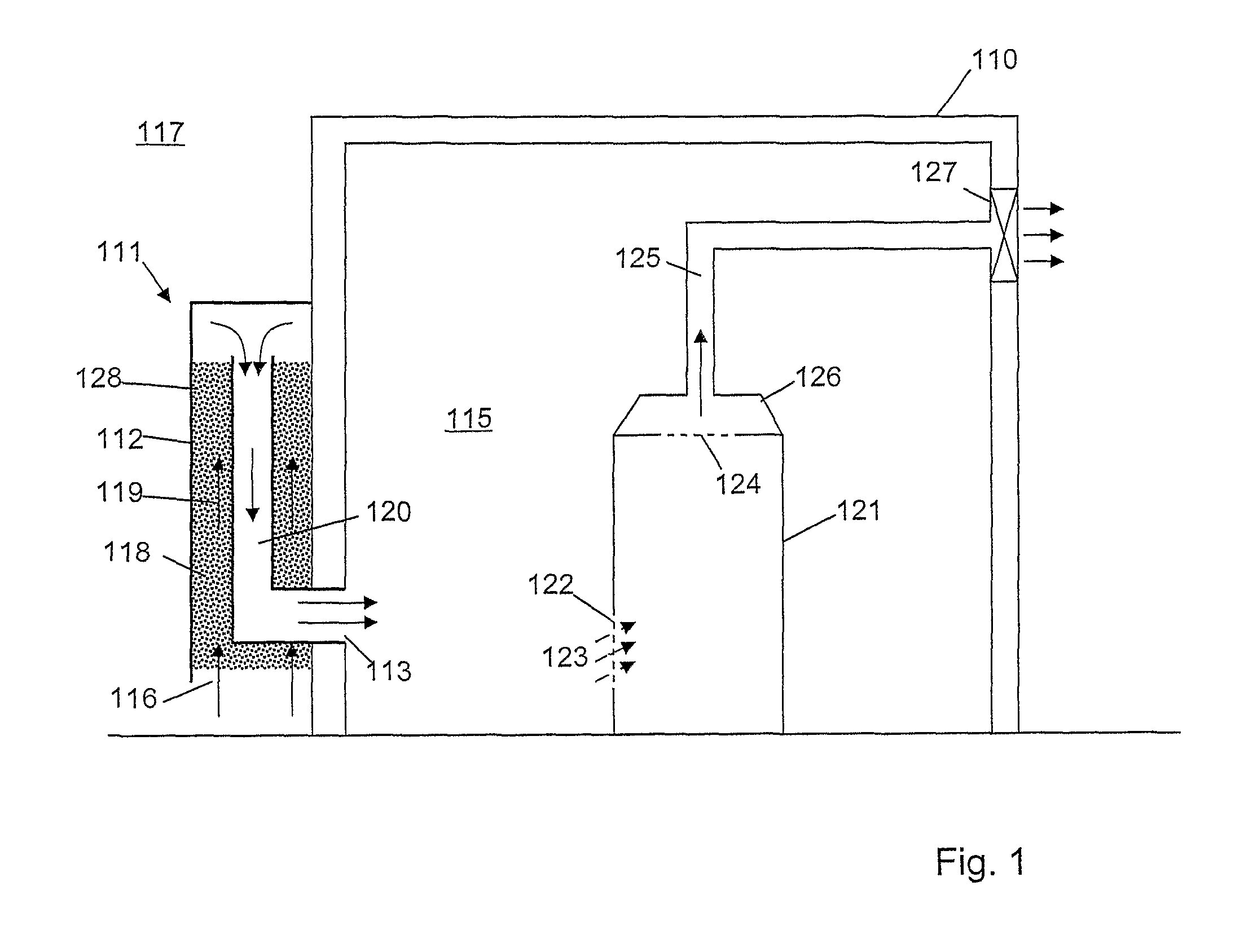
[0021]FIG. 1 illustrates in schematic cross-section an equipment room having air cooling;

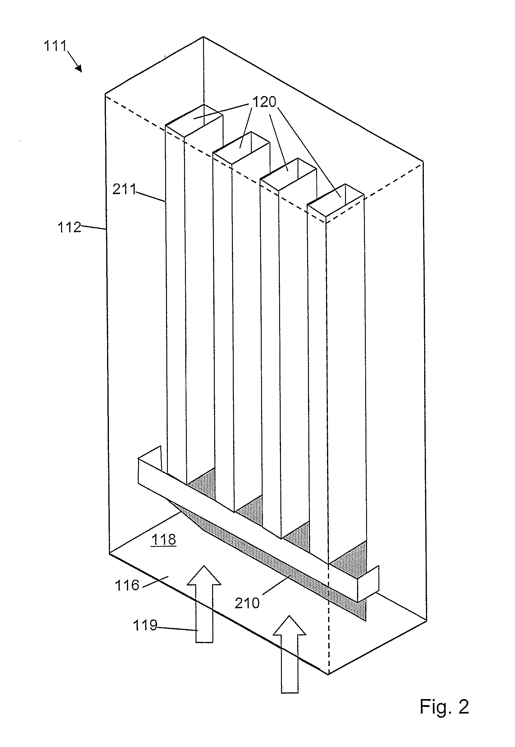
[0022]FIG. 2 illustrates a partial schematic isometric view of an exemplary air filter;

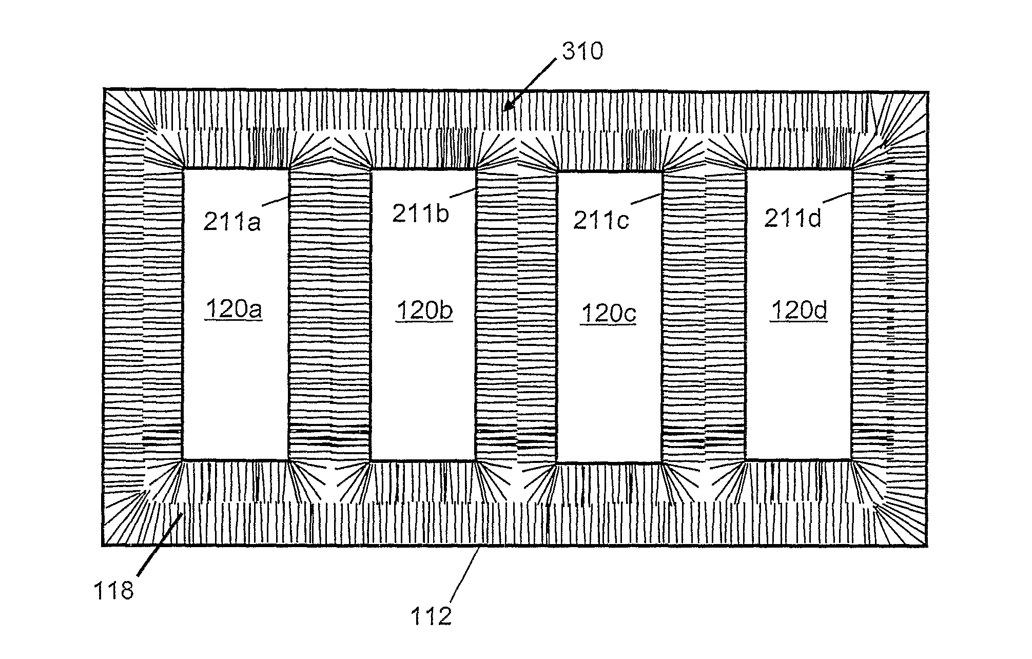
[0023]FIG. 3 illustrates a schematic cross-sectional representation of an inlet passageway of an exemplary air filter;

[0024]FIG. 4 illustrates a schematic cut-away view of an alternative exemplary air filter configuration;

[0025]FIG. 5 is a perspective view of an exemplary air filter body;

[0026]FIG. 6a is an elevation view of the air filter body;

[0027]FIG. 6b is a side view of the air filter body;

[0028]FIG. 7 is a schematic diagram of an equipment room comprising an exemplary air filter inlet arrangement; and

[0029]FIG. 8 is a further schematic diagram of an equipment room comprising an exemplary air filter inlet arrangement.

[0030]Illustrated in FIG. 1 is a schematic cross-sectional view of an eq...


PUM

PropertyMeasurementUnit
Lengthaaaaaaaaaa
Flow rateaaaaaaaaaa
Volumeaaaaaaaaaa

Abstract

An air filter (111) comprising a duct (118, 120) forming a passageway extending between an inlet (116) and an outlet (113) of the air filter, the duct comprising bristles (310) extending from a wall of the duct across at least a portion of the passageway so as to remov entrained particles from air passing through the duct.

Description

FIELD OF THE INVENTION[0001]The invention relates to air filters for use in ventilation and temperature control of, for example, electrical equipment enclosures.BACKGROUND[0002]Enclosures for electrical equipment typically require ventilation to allow the equipment to expel waste heat to an external environment to avoid overheating. In applications where electrical equipment is to be used in remote locations, for example in mobile radio telecommunications base stations, equipment is typically left unattended for extended periods. To ensure that the temperature of the equipment is kept within a preferred temperature range, additional cooling and ventilation apparatus is normally required. Depending on complexity, this cooling equipment consumes energy, which is both expensive and sometimes in limited supply, and also require maintenance to avoid the costly implications of failure.[0003]In a typical radio telecommunications base station, electrical equipment operating the radio freque...

Claims


Application Information

Patent Timeline
IPC IPC(8): H05K5/02B01D46/28
CPCB01D46/28H05K7/2059H05K7/20181B01D35/10F24F3/16F24F7/04
Inventor TINDALE, PATRICK ARTHURREDSHAW, PETER STUART
Owner 4ENERGY LTD
Why Eureka
Try Eureka