System and method for power management and load shedding

a power management and load shedding technology, applied in non-electric variable control, process and machine control, instruments, etc., can solve the problems of insufficient and excessive load shedding, slow response time to disturbances, and knowledge base that requires expensive computation engines

Inactive Publication Date: 2010-12-09
PROSAFE PRODION
View PDF2 Cites 33 Cited by
  • Summary
  • Abstract
  • Description
  • Claims
  • Application Information

AI Technical Summary

Benefits of technology

[0022]In accordance with a second aspect of the present invention there is provide a power management and load shedding system comprising a plurality of digital relays connected at respective generators and loads of a power system; a PLC connected to the digital relays via a communication link, the PLC substantially continuously obtaining data from the relays for calculating a reserve power, RP as RP=APT−APh−GPT, where APT is a total generation capacity of a plurality of running generators in a power system, APh is a highest capacity of any one of the running generators, and GPT is the total current gener

Problems solved by technology

Power consumption and production must balance at all times as any significant imbalance could cause instability or severe voltage fluctuations within the power system and lead to failures.
The drawback of this system is that the PLC executes the load shedding sequentially based on a pre-defined load priority table.
The process is independent of dynamic changes in the system loading, generation, or operating condition and this could result in insufficient and excessive load shedding.
Also, the nature of the sequential shedding results in slow response times to disturbances.
This self-learning and automatic trai

Method used


Image

  • System and method for power management and load shedding
  • System and method for power management and load shedding
  • System and method for power management and load shedding

Examples


Embodiment Construction

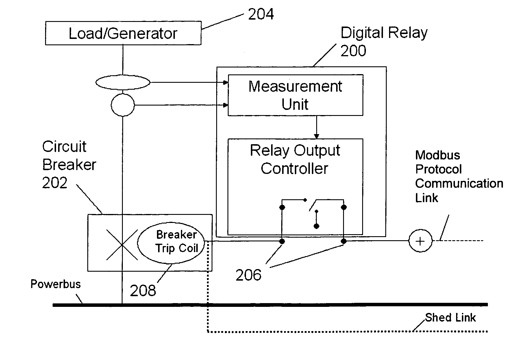
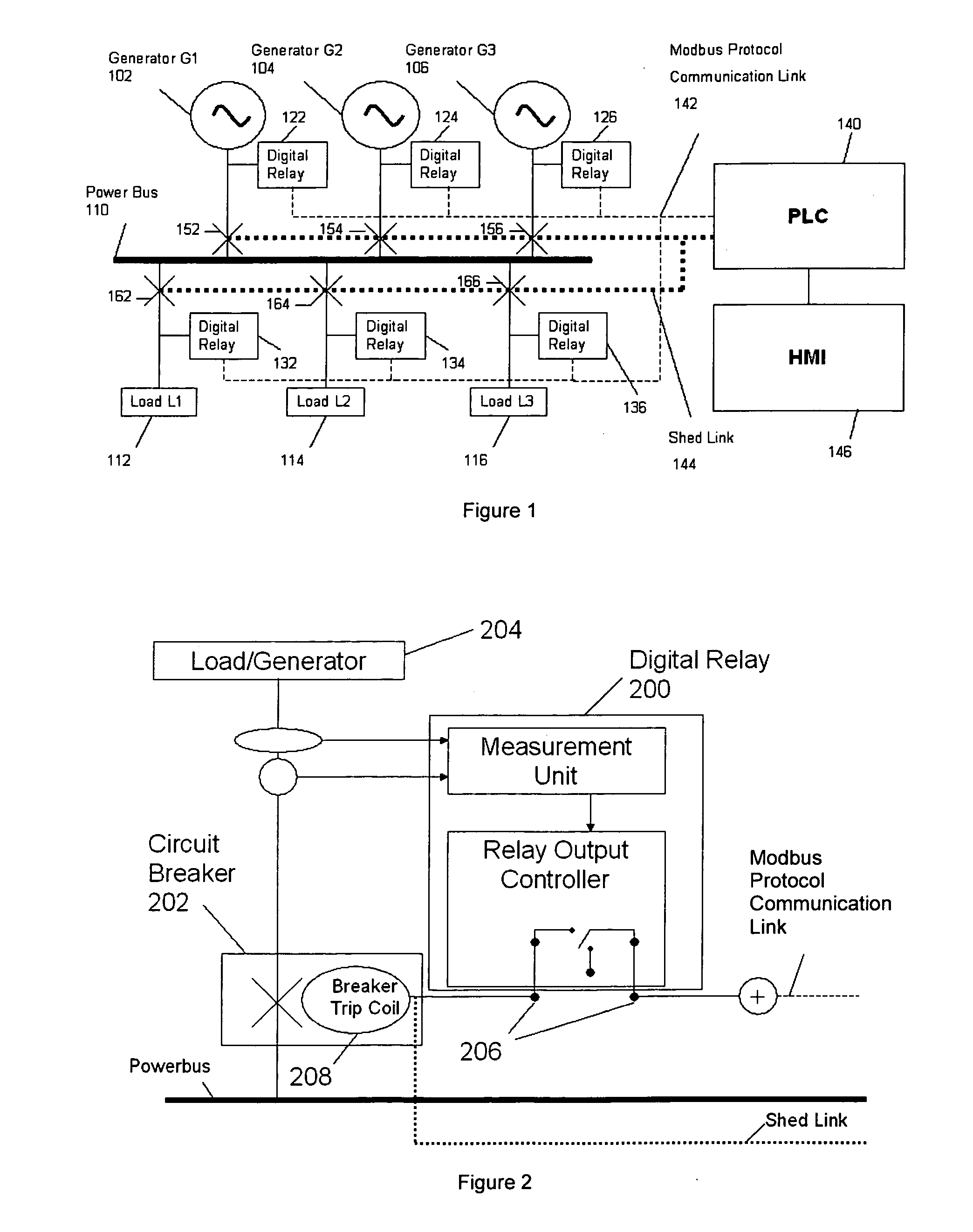
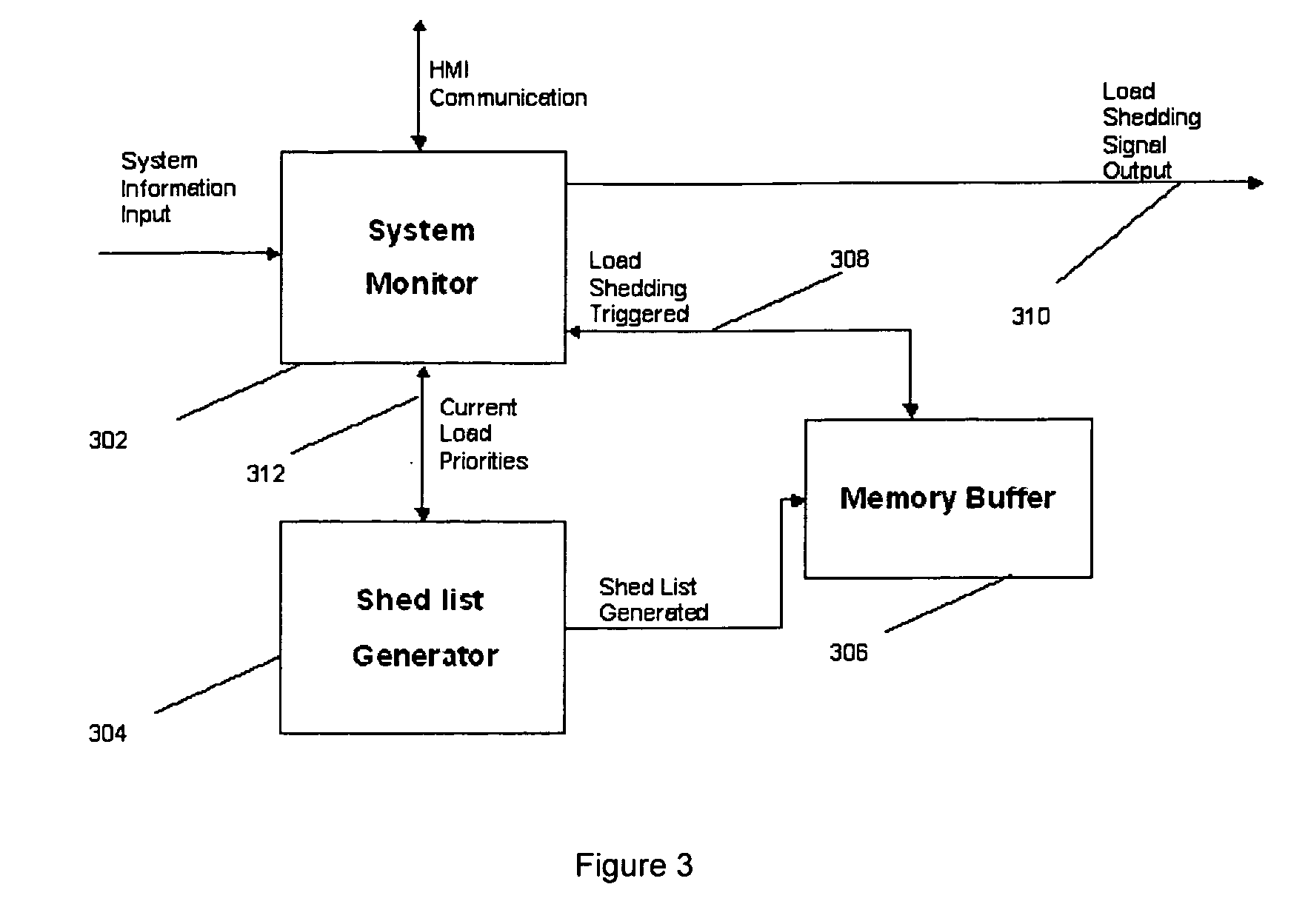
[0031]An example embodiment of the present invention discloses a system for power management and load shedding at an offshore platform or an FPSO. The system exploits the capability of modern digital relays to provide status and metered parameters of each major load and generator. Through modbus communication, the information is retrieved from digital relays and delivered to a specially developed Programmable Logic Circuit (PLC). This PLC provides two functions associated with Power Management Systems (PMS), namely system monitoring and shed list generation. The PLC may also display the information through a shared HMI (Human Machine Interface) for process control. At the HMI, information for each major load and generator may be displayed in the form of a network graphic with parameter thresholds. Whenever necessary, users may control the loads and generators through the HMI and manually override any automated load shedding sequences or enter and edit load priorities.

[0032]An exampl...


PUM


Abstract

A power management and load shedding method and system comprises the steps of:
    • a) Calculating a reserve power, RP as:
RP=APT−APh−GPT
    • where APT is a total generation capacity of a plurality of running generators in a power system, APh is a highest capacity of any one of the running generators, and GPT is a total current generated power from the running generators;
    • b) if the reserve power, RP, is negative, generating a load shedding list identifying one or more loads of the power system to be shed substantially simultaneously, such that a total power consumption of the loads in the load shedding list is equal to or greater than a deficit in the reserve power, RP;
    • c) storing the load shedding list in a buffer;
    • substantially continuously repeating steps a) to c); and
    • shedding the loads identified in the load shedding list stored in the buffer on detection of a failure of any one of the generators.

Description

CROSS-REFERENCE TO RELATED APPLICATIONS[0001]This application is the U.S. National Phase, under 35 U.S.C. 371, of PCT / SG 2007 / 000424, filed Dec. 6, 2007, and published as WO 2009 / 072985 A1 on Jun. 11, 2009, the disclosures of which are expressly incorporated herein by reference.FIELD OF INVENTION[0002]The present invention relates broadly to a power management and load shedding method and system.BACKGROUND[0003]In power management systems, there is a need to maintain stability in the system. Power consumption and production must balance at all times as any significant imbalance could cause instability or severe voltage fluctuations within the power system and lead to failures. The process of stabilising the system is usually achieved through load shedding. Load shedding refers to the reduction of load in response to generation deficiency conditions caused by unexpected system disturbances. Examples of these disturbances could be in the form of lightning strikes, loss of generation, ...

Claims


Application Information

Patent Timeline
IPC IPC(8): G01R11/00
CPCH02J3/14Y02B70/3225Y04S20/222H02J2310/60H02J3/144
Inventor KUMAR, BALESH
Owner PROSAFE PRODION
Why Eureka
Try Eureka