Apparatus for managing energy supplied to functional device units realizing a specific function

Active Publication Date: 2010-12-09
DENSO CORP
View PDF10 Cites 48 Cited by
  • Summary
  • Abstract
  • Description
  • Claims
  • Application Information

AI Technical Summary

Benefits of technology

[0011]The present invention has been made in order to resolve the above issue, and has as its object to provide an energy management apparatus

Problems solved by technology

In such a hybrid vehicle, however, the vehicle interior cannot be heated using the heat generated by the internal combustion engine when the internal combustion engine is not in operation.
However, no principle has been established regarding which of the functional device units should be preferentially used.
Not only the hybrid vehicles mentioned above but also those systems which are provided with two or more functio

Method used


Image

  • Apparatus for managing energy supplied to functional device units realizing a specific function
  • Apparatus for managing energy supplied to functional device units realizing a specific function
  • Apparatus for managing energy supplied to functional device units realizing a specific function

Examples


first embodiment

[0073]First, referring to FIGS. 1 to 6, hereinafter is described an energy management apparatus according to a first embodiment of the present invention. In the first embodiment, the energy management apparatus is applied to a parallel-hybrid vehicle.

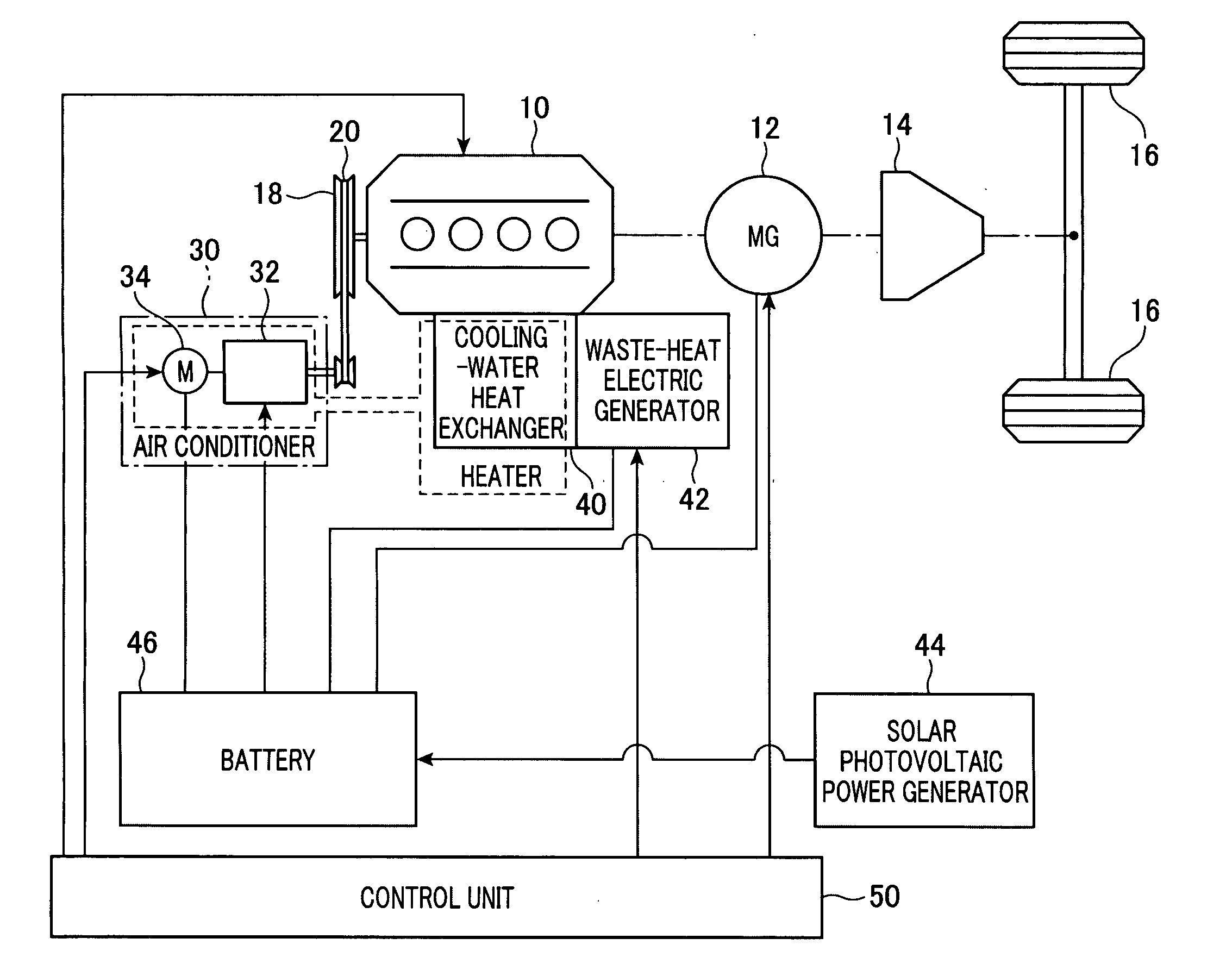
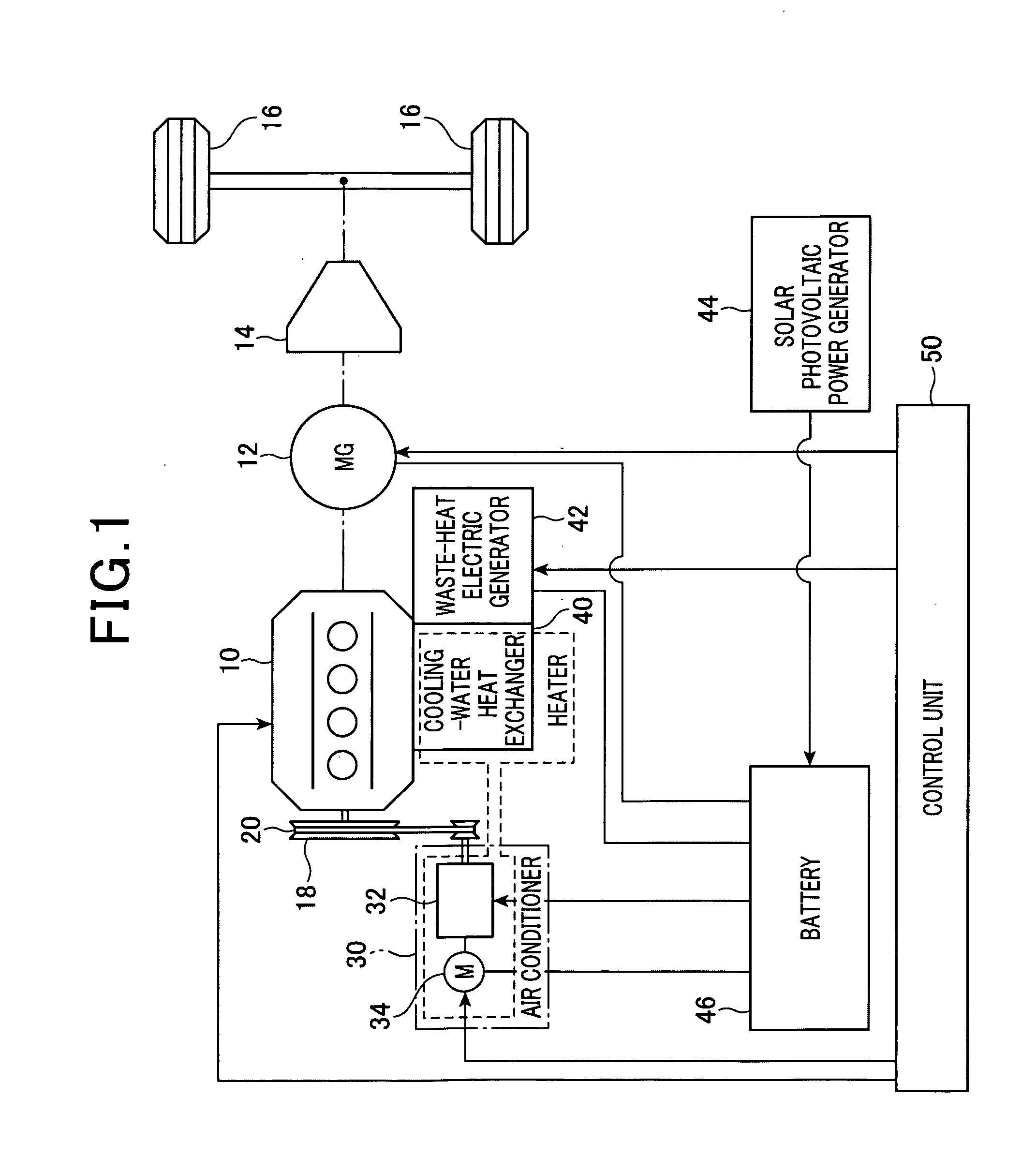
[0074]FIG. 1 is a schematic diagram illustrating the energy management apparatus according to the first embodiment. As shown in FIG. 1, the energy management apparatus includes an engine 10, motor-generator 12, transmission 14, drive wheels 16, pulley 18, belt 20, on-vehicle air conditioner 30, compressor 32, motor 34, cooling-water heat exchanger 40 (hereinafter just referred to as “heat exchanger 40”), waste-heat electric generator 42, solar photovoltaic power generator 40, battery 46 and control unit 50.

[0075]The engine 10 is an internal combustion engine that functions as an on-vehicle main engine. The engine 10 has a rotary shaft (crank shaft) which is directly connected to a rotary shaft of the motor-generator 12. The motor-genera...

second embodiment

[0131]With reference to FIG. 7, hereinafter will be described a second embodiment of the present invention, focusing on the differences from the first embodiment. It should be appreciated that, in the second and the subsequent various embodiments, the components identical with or similar to those in the first embodiment are given the same reference numerals for the sake of omitting explanation.

[0132]In the second embodiment, the average cost CE of the electric power domain is coupled with future prediction information of the environments where the vehicle concerned will be situated.

[0133]FIG. 7 shows a procedure of calculating the average cost CE, according to the present embodiment. For example, this procedure is repeatedly performed at a predetermined cycle.

[0134]In a series of processes in the procedure, it is determined, at step S60, whether or not environmental information of near future (e.g., future of several minutes to two hours later) is available. The environmental inform...

third embodiment

[0139]With reference to FIG. 8, hereinafter is described a third embodiment, focusing on the differences from the first embodiment.

[0140]Use of the waste-heat heater may raise a problem if the engine 10 has not been warmed up. The problem in this case is that sufficient heat may not be obtained until the engine 10 is warmed up. Therefore, in this case, the efficiency of the engine 10 is lowered in order to secure heat in a transition period preceding a quasi-equilibrium state (quasi-static state). Then, the engine efficiency is gradually raised to calculate the system cost. However, such a calculation may increase the calculation load of the control unit 50.

[0141]In this regard, in the present embodiment, the engine 10 is assumed to be in a quasi-static state when waste-heat heating is estimated while the engine 10 is stopped. Thus, the calculation of the cost that will be incurred in the system can be simplified.

[0142]FIG. 8 shows a procedure of selecting a functional device unit t...


PUM


Abstract

An energy management apparatus is used to manage energy to be supplied to a system. A paid energy resource can be supplied to the system from the outside. The system is provided with two or more functional device units realizing a specific function using the input energy and adapted to satisfy an external request using at least one of the two or more functional device units such that supply of energy to the functional device units can be controlled. In the apparatus, a standardizing means standardizes input energy of each of the two or more functional device units in terms of the cost of the paid energy resource required for producing the input energy. In addition, a determining means determines to which of the two or more functional device units a predetermined quantity of energy should be fed such that the cost incurred in the system can be reduced.

Description

CROSS-REFERENCE TO RELATED APPLICATION[0001]This application is based on and claims the benefit of priority from earlier Japanese Patent Application No. 2009-136541 filed Jun. 5, 2009, the description of which is incorporated herein by reference.BACKGROUND OF THE INVENTION[0002]1. Technical Field of the Invention[0003]The present invention relates to an energy management apparatus for managing energy to be supplied to a system, to which a paid energy resource can be supplied from outside, which is provided with two or more functional device units realizing a specific function using the input energy and satisfies an external request using at least one of the two or more functional device units, so that supply of energy to the functional device units can be controlled.[0004]2. Related Art[0005]In recent years, various techniques have been developed in terms of reducing energy consumption and the like in vehicles. For example, so-called hybrid vehicles have been developed, which are eq...

Claims


Application Information

Patent Timeline
IPC IPC(8): B60W20/00G06F19/00G06F1/26B60H1/22B60K6/48B60K6/54B60L7/10B60L50/16B60W10/06B60W10/08B60W10/30
CPCB60K6/48B60K16/00B60K2016/003B60W10/06B60W10/08B60W10/30Y02T10/84Y02T10/6221Y02T10/6286B60W20/10B60W10/26Y02T10/90B60W20/00Y02T10/62
Inventor OBAYASHI, KAZUYOSHISAKAMOTO, AKIRA
Owner DENSO CORP
Why Eureka
Try Eureka