Method for detecting a level of contamination of a particle sensor, and particle sensor

a technology of particle sensor and detection method, which is applied in the direction of chemical methods analysis, instruments, material analysis, etc., can solve the problems of ash particles, also accumulate on the particle sensor, and achieve the effect of improving the resolution capability

Inactive Publication Date: 2010-12-09
ROBERT BOSCH GMBH
View PDF5 Cites 26 Cited by
  • Summary
  • Abstract
  • Description
  • Claims
  • Application Information

AI Technical Summary

Benefits of technology

[0015]It is particularly preferred that the heating period is longer than the cooling period during modulation. This allows the insulator material to be simultaneously heated above the limiting temperature during modulation. It is not necessary to know an instantaneous temperature of the insulator material. Instead, it may ascertained in a particularly simple manner that the limiting temperature has been exceeded to

Problems solved by technology

A disadvantage of this type of particle sensor is that ash particles, which do not burn o

Method used


Image

  • Method for detecting a level of contamination of a particle sensor, and particle sensor
  • Method for detecting a level of contamination of a particle sensor, and particle sensor
  • Method for detecting a level of contamination of a particle sensor, and particle sensor

Examples


Embodiment Construction

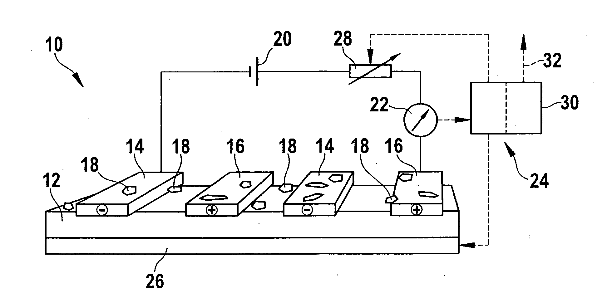
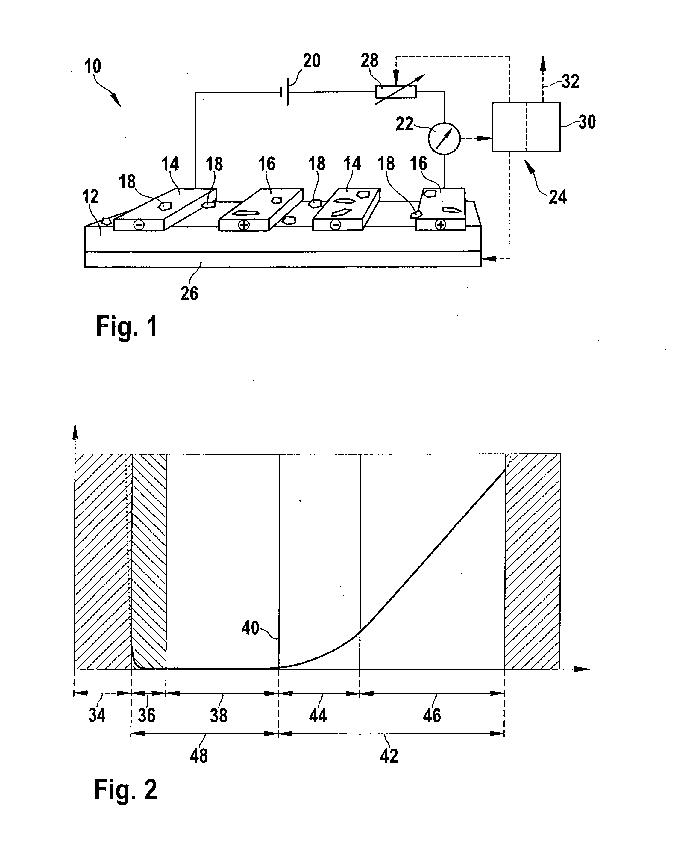
[0023]Particle sensor 10 illustrated in FIG. 1 has an insulator material 12 on which a first electrode 14 and a second electrode 16 are situated in alternation. During operation of particle sensor 10 ash particles 18 accumulate on insulator material 12 and electrodes 14, 16, which may result in an electrical shunt between first electrode 14 and second electrode 16. A power source 20 is situated between first electrode 14 and second electrode 16 for generating an electrical field between electrodes 14, 16. The resistance between electrodes 14, 16 and / or the current flowing between electrodes 14, 16 may be detected using a measuring device 22.

[0024]The variation over time of the measuring signal measured by measuring device 22 is processed in a control unit 24. Control unit 24 may also control a heating apparatus 26 in order to heat insulator material 12 above a limiting temperature at which insulator material 12 begins to become conductive, and to modulate between a lower temperature...


PUM


Abstract

In a method for detecting a level of contamination of a particle sensor provided with two electrodes situated on an insulator material for generating an electrical field, the insulator material is heated to above a limiting temperature of the insulator material at which the insulator material begins to become conductive. The insulator material is modulated by heating or cooling, the modulation being carried out at a lower temperature and an upper temperature which are each above the limiting temperature. The variation over time of a measuring signal which may be picked up between electrodes is measured during the modulation. The measured variation over time of the measuring signal is compensated using a theoretical variation over time of the measuring signal in a contamination-free state of the particle sensor in order to obtain a variation over time of a differential signal.

Description

BACKGROUND OF THE INVENTION[0001]1. Field of the Invention[0002]The present invention relates to a method for detecting a level of contamination of a particle sensor, and a particle sensor that is suitable therefor, with the aid of which, for example, soot particles in an exhaust gas stream of a motor vehicle may be detected.[0003]2. Description of Related Art[0004]A resistive particle sensor is known from published German patent application document DE 10 2005 053 120 A1 which has two comb electrodes situated on an insulator material for generating an electrical field. The particle sensor is situated in an exhaust gas stream of a motor vehicle so that soot particles may accumulate between the two electrodes. After a given time (blind period), enough soot particles have accumulated so that a current, which may be detected using a measuring device, is able to flow between the two electrodes. The measuring signal which is obtainable from the measuring device is proportional to the acc...

Claims


Application Information

Patent Timeline
IPC IPC(8): G06F19/00G01N25/00
CPCG01N15/0606G01N15/0656
Inventor DIEHL, LOTHARKUHN, BETTINASCHITTENHELM, HENRIK
Owner ROBERT BOSCH GMBH
Why Eureka
Try Eureka