Three Dimensional Air Flow Sensors for Data Center Cooling

a data center and air flow sensor technology, applied in the field of airflow analysis, can solve the problems of complex measurement and more of a challenge in cooling them

Active Publication Date: 2010-12-09
GLOBALFOUNDRIES US INC
View PDF25 Cites 22 Cited by
  • Summary
  • Abstract
  • Description
  • Claims
  • Application Information

AI Technical Summary

Problems solved by technology

However, as data centers become increasingly larger in size, cooling them becomes more of a challenge.
However, air movement is generally characterized by both airflow velocity and direction,

Method used


Image

  • Three Dimensional Air Flow Sensors for Data Center Cooling
  • Three Dimensional Air Flow Sensors for Data Center Cooling
  • Three Dimensional Air Flow Sensors for Data Center Cooling

Examples


Embodiment Construction

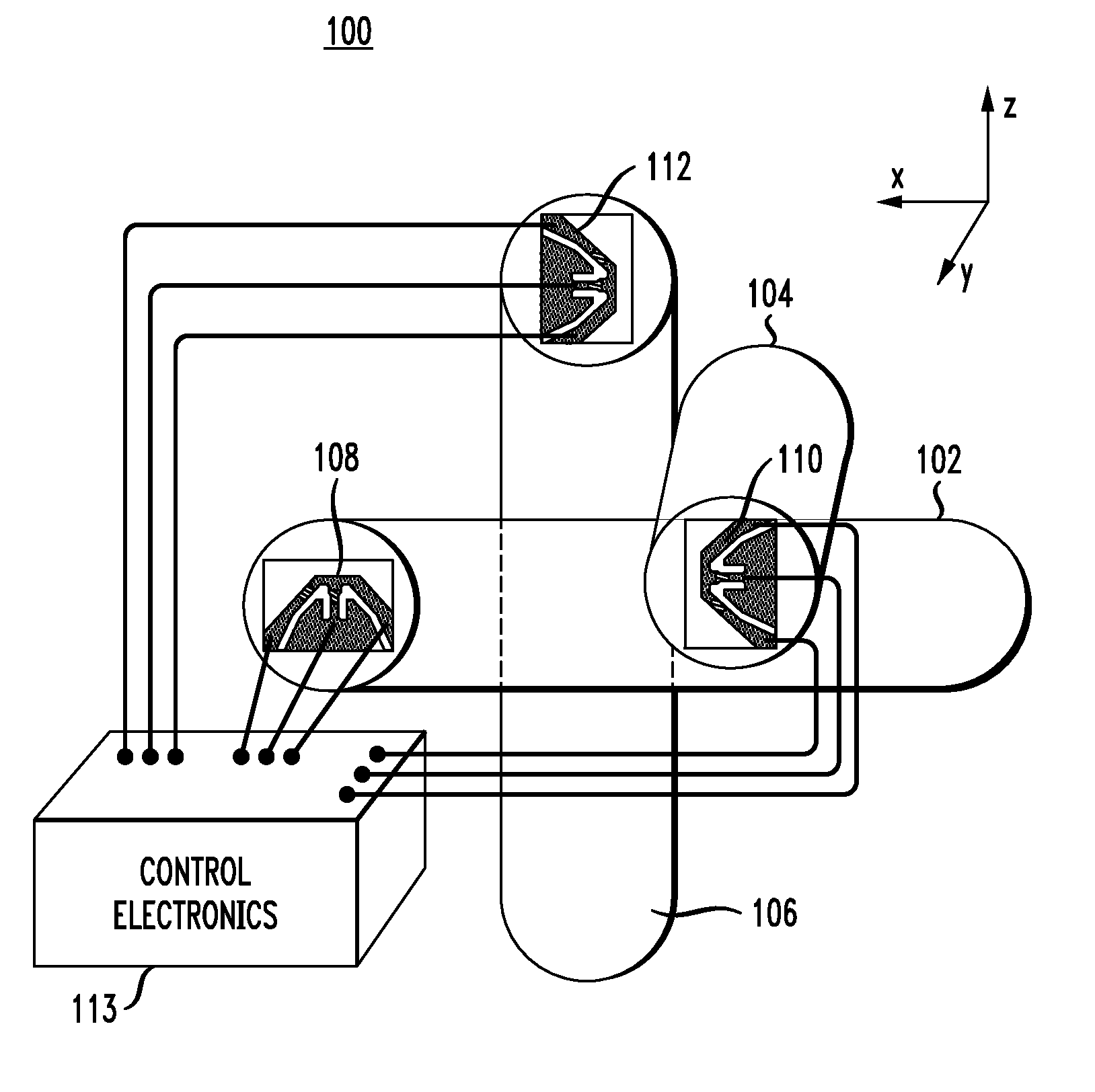
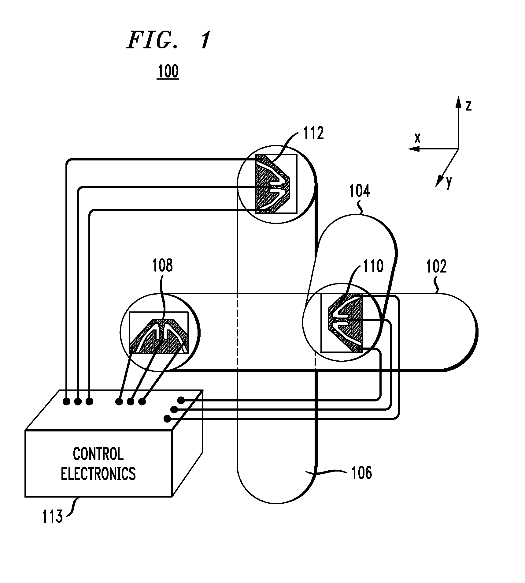
[0023]FIG. 1 is a diagram illustrating exemplary airflow sensing unit 100. Airflow sensing unit 100 comprises a first air passage 102, a second air passage 104 and a third air passage 106. As shown in FIG. 1, air passage 102 and air passage 104 are perpendicular to one another, and air passage 106 is perpendicular to air passage 102 and air passage 104. By way of example only, if air passage 102 is positioned along an x-axis and air passage 104 is positioned along a y-axis, then air passage 106 would be positioned along a z-axis. According to an exemplary embodiment, the air passages include tubes that constrain air flow along a predefined direction. The tubes are separate from one another, with one tube for each direction. When the air passages include tubes, each tube should have a large enough diameter to be able to sample airflow velocity without disturbing the airflow (in a laminar flow regime). The diameter of the tube will determine the resolution, i.e., how fine a sampling o...


PUM


Abstract

Techniques for airflow analysis are provided. In one aspect, a mobile sensing device is provided. The mobile sensing device includes an airflow sensing system having a plurality of airflow sensing units arranged in a grid. Each airflow sensing unit includes a first air passage that contains at least one first airflow sensor; a second air passage perpendicular to the first air passage, wherein the second air passage contains at least one second airflow sensor; and a third air passage perpendicular to the first air passage and the second air passage, wherein the third air passage contains at least one third airflow sensor.

Description

FIELD OF THE INVENTION[0001]The present invention relates to airflow analysis, and more particularly, to techniques for making three dimensional airflow measurements in a room, such as a data center.BACKGROUND OF THE INVENTION[0002]In data centers, heat is generated by continuous and simultaneous operation of a large number of computing unit racks. Air cooling the whole room containing the data center is the most common method used to maintain thermal operating conditions in the data center. However, as data centers become increasingly larger in size, cooling them becomes more of a challenge. Thus, efficient heat dissipation and removal techniques have been pursued to reduce electrical power usage and to optimize operating performance.[0003]Advances such as mobile measurement technology (MMT) have been proposed to measure temperature distributions and air flow in data centers to locally detect and cool areas with temperatures well above a desired level. See, for example, U.S. Pat. N...

Claims


Application Information

Patent Timeline
IPC IPC(8): G01F1/68G01F1/00
CPCG01F1/6842G01F1/6845F24F2110/30G01P13/02G01P5/12
Inventor HAMANN, HENDRIK F.KLEIN, LEVENTE
Owner GLOBALFOUNDRIES US INC
Why Eureka
Try Eureka