Rotation transmission device

a transmission device and rotational direction technology, applied in the direction of mechanical actuated clutches, bearing unit rigid support, interlocking clutches, etc., can solve the problems of inability to completely eliminate such rollers tend to get engaged in errors, and the two-way clutch cannot be idled with high reliability, so as to minimize play in the rotational direction, and increase the circumferential width of the pockets

Inactive Publication Date: 2010-12-16
NTN CORP
View PDF9 Cites 43 Cited by
  • Summary
  • Abstract
  • Description
  • Claims
  • Application Information

AI Technical Summary

Benefits of technology

[0030]According to the first invention, when the electromagnetic clutch is activated and the control retainer is moved in the direction in which its flange moves away from the flange of the rotary retainer, the control retainer and the rotary retainer rotate relative to each other in the direction to increase the circumferential width of the pockets under the biasing force of the coil springs. This causes the opposed pairs of rollers to be instantly wedged into the narrow ends of the wedge-shaped spaces. Thus, it is possible to minimize play in the rotational direction in the rotation transmission device.
[0031]When the control retainer is moved in the direction in which its flange moves toward the flange of the rotary retainer, the torque cam is activated such that the control retainer and the rotary retainer rotate relative to each other to increase the circumferential width of the pockets. Thus, the opposed pairs of rollers are pushed by the bridges of the control retainer and the rotary retainer, and disengage. In this disengaged state, the bridges of the control retainer and the rotary retainer prevent the opposed pairs of rollers from being pushed into the narrow ends of the wedge-shaped spaces, which in turn prevents the rollers from getting engaged in error while the two-way roller clutch is idling. This ensures reliable idling of the two-way roller clutch.
[0032]Since turning torque is transmitted from the inner ring to the outer ring through as many rollers as the cam surfaces, the rotation transmission device has a large torque capacity.
[0033]According to the second invention, when the control retainer is moved away from the rotary retainer, the control retainer and the rotary retainer rotate relative to each other in the direction to increase the circumferential width of the pockets under the biasing force of the coil springs. This causes the opposed pairs of rollers to be instantly wedged into the narrow ends of the wedge-shaped spaces. Thus, as in the first invention, it is possible to minimize play in the rotational direction in the rotation transmission device.
[0034]When the control retainer is moved toward the rotary retainer, the opposed pairs of rollers are pushed by the bridge portions of the control retainer and the rotary retainer, and disengage. In this disengaged state, the bridge portions of the control retainer and the rotary retainer prevent the opposed pairs of rollers from being pushed into the narrow ends of the wedge-shaped spaces, which in turn prevents the rollers from getting engaged in error while the two-way roller clutch is idling. This ensures reliable idling of the two-way roller clutch.

Problems solved by technology

With the two-way roller clutch disclosed in Patent Document 2, while it is possible to reduce play in the rotational direction, it is impossible to completely eliminate such play in the rotational direction.
Also, since the gaps between the rollers and the outer ring cylindrical surface and between the rollers and the inner ring cam surfaces are small, the rollers tend to get engaged in error while the two-way clutch is idling.
Thus, the two-way clutch cannot be idled with high reliability.
Also, while torque is being transmitted between the outer ring and the inner ring, since only half the rollers are engaged while the remaining half of the rollers are disengaged, the torque capacity is low.

Method used


Image

  • Rotation transmission device
  • Rotation transmission device
  • Rotation transmission device

Examples


first embodiment

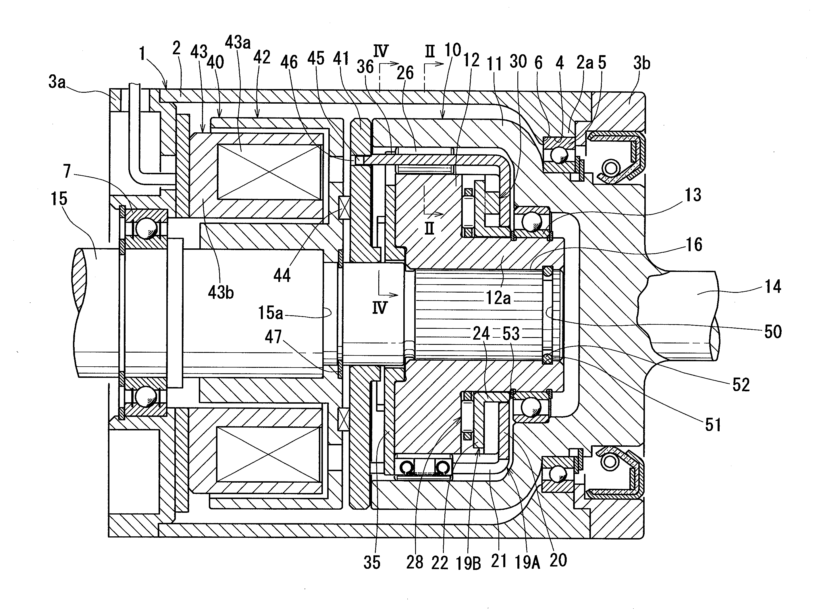
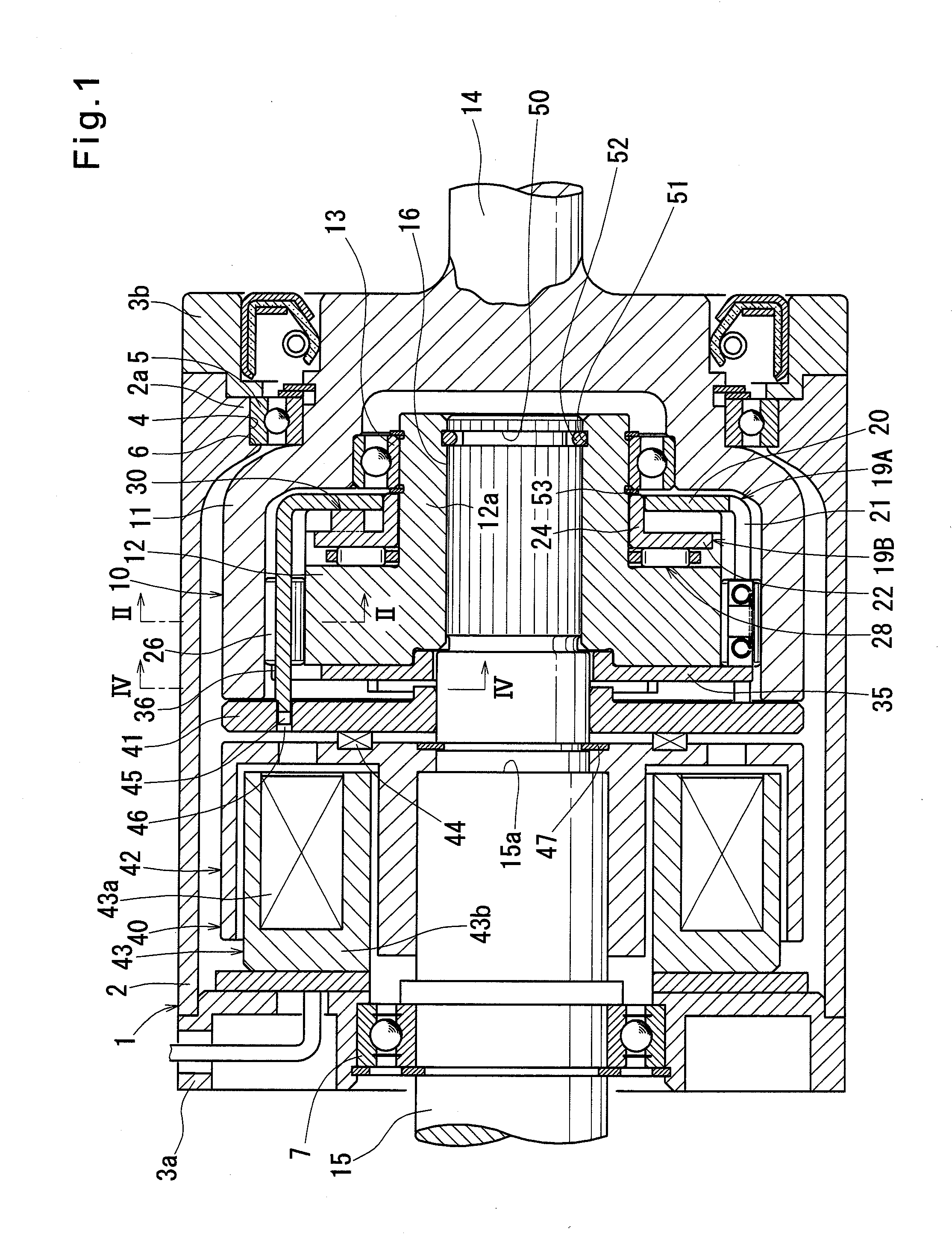
[0123]Now the operation of the rotation transmission device of the first embodiment is described. FIG. 1 shows the state in which the electromagnetic coil 43a of the electromagnet 43 is off and thus the armature 41 is separated from the rotor 42 by the separation spring 44. In this state, the two-way roller clutch 10 is engaged, with its opposed pairs of rollers 26 kept in engagement with the cylindrical surface 17 of the outer ring 11 and the cam surfaces 18 of the inner ring 12, as shown in FIG. 2(I).

[0124]With the two-way roller clutch 10 engaged, when the electromagnetic coil 43a is energized, attraction force acts on the armature 41 and axially moves the armature 41 until it is pressed against the rotor 42.

[0125]Since the armature 41 is fixedly coupled to the bridges 21 of the control retainer 19A, when the armature 41 moves axially, the control retainer 19A moves in the direction in which its flange 20 moves toward the flange 22 of the rotary retainer 19B.

[0126]When the retain...

second embodiment

[0153]FIGS. 13 to 17 show the rotation transmission device according to embodiment of the present invention. As with the rotation transmission device of FIG. 1, this embodiment includes a two-way roller clutch 2 mounted in a housing 1, and an electromagnetic clutch 40 also mounted in the housing 1 for selectively engaging and disengaging the two-way roller clutch 10.

[0154]As with the two-way roller clutch 10 of the first embodiment, the two-way roller clutch 10 of the second embodiment includes a retainer 80 mounted between the cylindrical surface 17 on the inner periphery of an outer ring 11, and the cam surfaces 18 on the outer periphery of the inner ring 12.

[0155]The retainer 80 is a cylindrical member having radially inwardly extending flange 80a and 80b at both ends thereof, and formed with pockets 81 facing the respective cam surfaces 18. Mounted in each pocket 81 are an opposed pair of rollers 26 and a plurality of coil springs 27 biasing the pair of rollers 26 away from each...


PUM


Abstract

A rotation transmission device is provided which is small in play in the rotational direction, can be idled with high reliability and is high in torque capacity.
An axially movable control retainer 19A and a rotatable rotary retainer 19B are mounted between an outer ring 11 having a cylindrical surface 17 on its inner periphery and an inner ring 12 having cam surfaces on its outer periphery. An opposed pair of rollers 26 and a coil spring 27 for biasing the pair of rollers 26 away from each other are received in each pocket 25 defined between bridges 21 and 23 of the respective retainers 19A and 19B. A torque cam 30 is provided between flanges 20 and 22 of the control retainer 19A and the rotary retainer 19B, respectively. An armature 41 is coupled to the bridges 21 of the control retainer 19A. An electromagnet 43 is provided to face a rotor 42 that axially faces the armature 41 so that when the electromagnet 43 is energized, the control retainer 19A moves toward the rotor 42, and the control retainer 19A and the rotary retainer 19B rotate relative to each other in the direction to reduce the circumferential width of the pockets 25, thereby disengaging the opposed pairs of rollers 26. When the electromagnet 43 is deenergized, the control retainer 19A moves away from the rotor 42 under the biasing force of the separation spring 44, and the control retainer 19A and the rotary retainer 19B rotate relative to each other in the direction to increase the circumferential width of the pockets 25, thereby engaging the opposed pairs of rollers 26.

Description

TECHNICAL FIELD[0001]This invention relates to a rotation transmission device used to selectively transmit power.BACKGROUND ART[0002]Patent Document 1 discloses a rotation transmission device used in an FR-based four-wheel drive vehicle for selectively transmitting driving force to the front wheels as auxiliary drive wheels.[0003]The rotation transmission device disclosed in Patent Document 1 includes a two-way clutch disposed between a large-diameter portion of an input member and an outer ring provided therearound, and an electromagnetic clutch provided beside the two-way clutch for selectively engaging and disengaging the two-way clutch, whereby when the two-way clutch is engaged, the input member is coupled to the outer ring, so that torque is transmitted between the input member and the outer ring.[0004]The outer ring of the two-way clutch has a cylindrical surface on its inner periphery, while cam surfaces are formed on the outer periphery of the large-diameter portion of the ...

Claims


Application Information

Patent Timeline
Patent Type & Authority Applications(United States)
IPC IPC(8): F16D11/04
CPCF16D41/105F16C35/063F16C2226/74
Inventor AKIYOSHI, KOJISATO, TAKANOBUSAITO, TAKAHIDE
Owner NTN CORP
Why Eureka
Try Eureka