
Radio communication method and radio communication device

a radio communication and radio communication technology, applied in the field of radio communication networks, can solve the problems of difficult movement, few major applications, and inability to say that the uwb is easy to use in the office environment, and achieve the effect of reducing standby power consumption

Inactive Publication Date: 2010-12-16
PANASONIC CORP
View PDF9 Cites 88 Cited by
  • Summary
  • Abstract
  • Description
  • Claims
  • Application Information

AI Technical Summary

Benefits of technology

[0022]According to the present invention, in an ad hoc network, a radio communication apparatus can reduce standby power consumption as compared with a conventional case, and super-frame synchronization adjustment becomes possible in a mobile environment. As a result, communication with another radio communication apparatus can be started in a minimal time.
[0023]Further, according to the present invention, it is possible to realize the coexistence of two or more radio communication schemes.

Problems solved by technology

On the other hand, UWB cannot be said to be easy to use in an office environment due to the narrowness of its possible communication range, and it can be said to be better suited to PANs (Personal Area Networks) that are attracting attention nowadays.
However, PANs are still in their early days, and there are very few major applications.
Since PANs have the broadband characteristics, a device utilizing PANs generally uses a lot of power, but in the case of a PAN, movement is difficult while carrying a large number of batteries.
This is because, in a PAN environment in which terminals constantly pass by each other, constructing a master-slave relationship each time, and starting communication after setting up a communication environment, such as assigning data slots, is a major overhead.
However, it is difficult to determine one scheme because these proposed schemes each have unique features.

Method used


Image

  • Radio communication method and radio communication device
  • Radio communication method and radio communication device
  • Radio communication method and radio communication device

Examples


embodiment 1

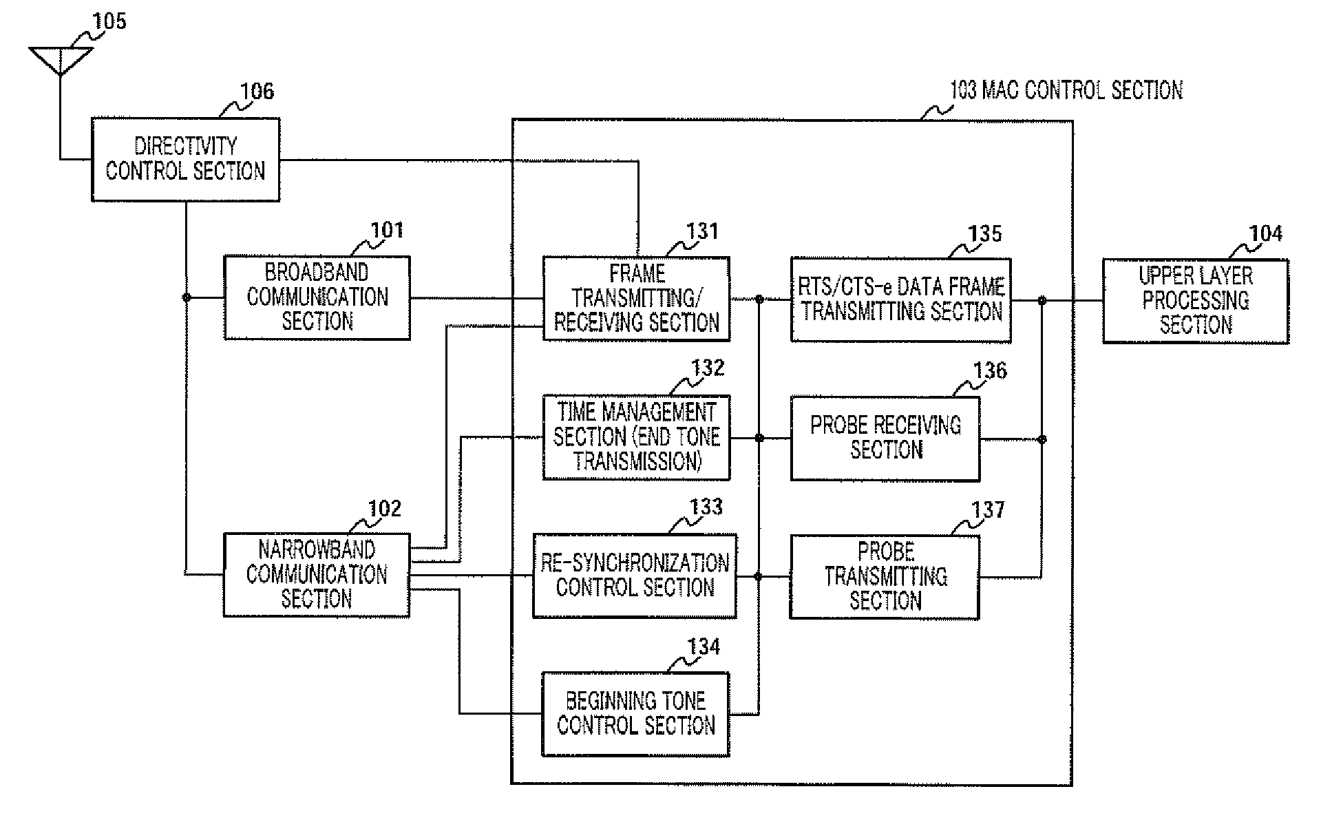
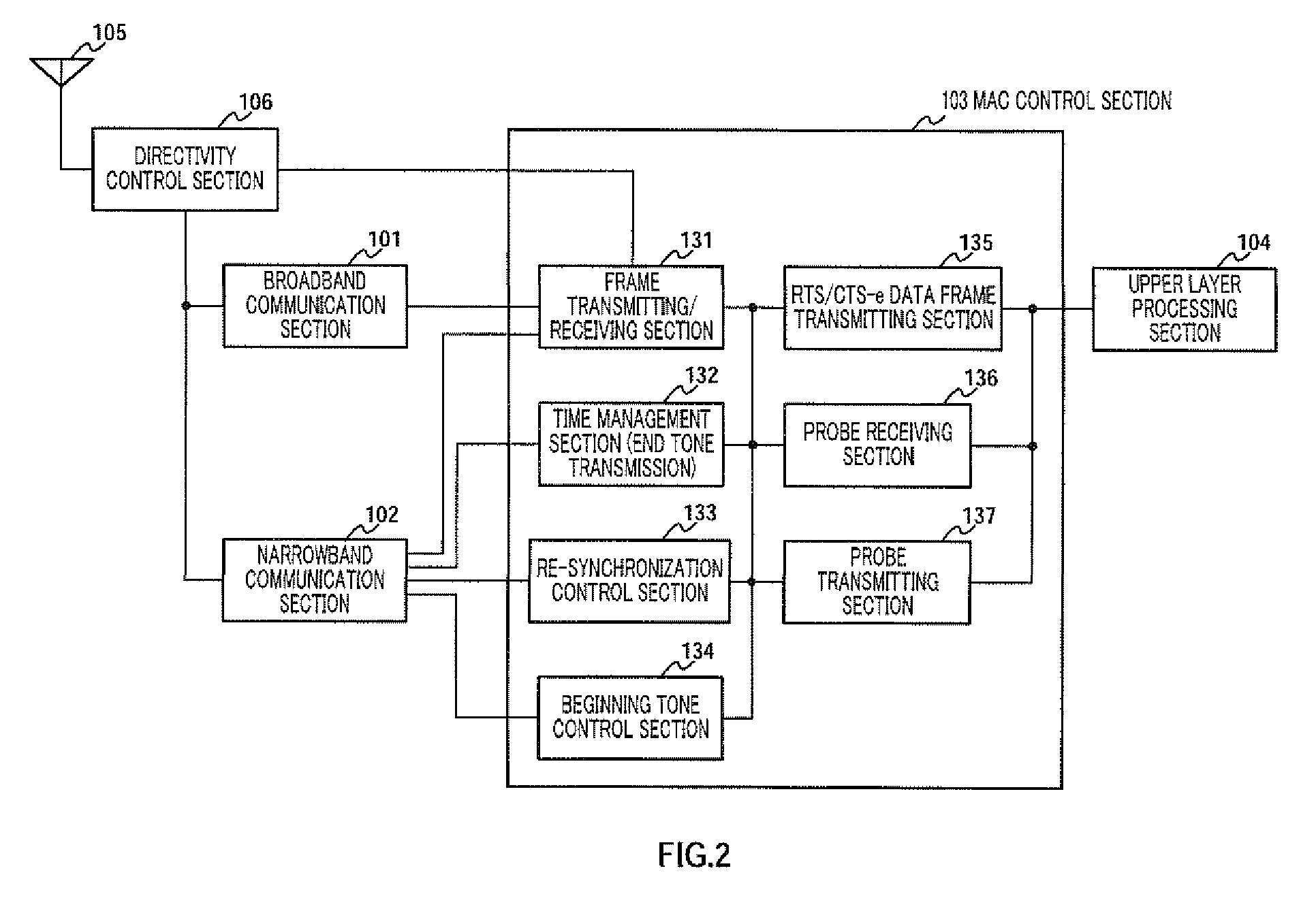
[0054]FIG. 2 is a configuration diagram of a radio communication apparatus according to this embodiment of the present invention.

[0055]In FIG. 2, the radio communication apparatus is equipped with an antenna 105, a directivity control section 106, a broadband communication section 101, a narrowband communication section 102, a MAC control section 103, and an upper-order layer processing section 104.

[0056]Antenna 105 comprises a plurality of directional antennas each responsible for a particular sector, and directivity control section 106 controls the directional antennas composing antenna 105 and determines the communication range. Broadband communication section 101 transmits and receives UWB signals, and narrowband communication section 102 transmits and receives narrowband signals with or without performing modulation. If a broadband signal is DS-UWB (Direct Sequence UWB), the respective transmitters may be shared, so as to widen the transmitted DS-UWB pulse width in order to tra...

embodiment 2

[0158]A radio communication apparatus according to this embodiment transmits a probe request, or returns a response, by means of a directional antenna to all surrounding nodes. The configuration of a radio communication apparatus according to this embodiment is identical to the configuration according to Embodiment 1, but the directional antenna communication range must be an area that allows all nodes of the probe request frame coverage area to communicate with each other. For example, when the directional antenna coverage area is an area of radius r, as shown in FIG. 17, a state is established in which arbitrary nodes B and C within a circle of radius r and with its center at a point r / 2 in the direction in which the antenna is facing can perform mutual transmission and reception. When a radio communication apparatus in such an arrangement issues a probe request, a response thereto can achieve collision avoidance by means of normal carrier sense.

[0159]A radio communication apparat...

embodiment 3

[0165]A radio communication method according to this embodiment uses a send / receive tone and end tone in the same way as in Embodiment 1, but differs in not using beginning tones 1 and 2.

[0166]FIG. 18 is a timing chart explaining the super-frame tone signals and frame according to this embodiment.

[0167]In FIG. 18, a super-frame 1501 is composed of end tone slots 1502 and a transmission / reception period 1503. There are only two tone signals—an end tone 1511 and a send / receive tone 1513—and a send / receive tone 1512 transmitted in an end tone re-synchronization slot 1504, which is a special time period after an end tone is transmitted, is given a special designation of “probe tone.”

[0168]A send / receive tone, when received by transmission / reception period 1503, gives notification of transmission / reception of a command or data by means of a broadband signal in the same way as in Embodiment 1.

[0169]However, send / receive tone 1512 received after end tone reception in an end tone slot gives...


PUM


Abstract

Provided is a radio communication method which can reduce the power consumption as compared to the conventional technique while realizing coexistence of a plurality of radio communication methods and can perform synchronization with a super frame of other radio communication device. The super frame has life confirmation slots (2820, 2830) through which radio communication devices of various modulation types should transmit tone signals. A radio communication device has a chance to judge whether one or more radio communication devices using a different modulation type exist or no such device exists in the vicinity. If no such device exists, the slot to be used by the radio communication device of the modulation method is reported as a time that can be used by a radio communication group of other modulation method. Thus, by confirming existence of an object in the vicinity by other radio communication device with which communication cannot be performed, communication can be performed by sharing the super frame.

Description

TECHNICAL FIELD [0001]The present invention relates to a radio communication network, and more particularly to ad hoc network communication in a mobile environment.BACKGROUND ART [0002]In recent years, various proposals have been made concerning UWB (Ultra Wide Band) radio communication methods. As UWB radio communication enables broadband communication exceeding 1 Gbps, its application to video transmission and the like with large transmission capacity has been investigated. On the other hand, UWB cannot be said to be easy to use in an office environment due to the narrowness of its possible communication range, and it can be said to be better suited to PANs (Personal Area Networks) that are attracting attention nowadays. However, PANs are still in their early days, and there are very few major applications. Since PANs have the broadband characteristics, a device utilizing PANs generally uses a lot of power, but in the case of a PAN, movement is difficult while carrying a large num...

Claims


Application Information

Patent Timeline
IPC IPC(8): H04J3/06H04B1/7183H04J13/00H04W28/06H04W56/00H04W68/12H04W84/18H04W92/18
CPCH04L27/0006H04W74/0816Y02D70/22Y02D70/144H04W84/18Y02D30/70
Inventor DOI, HIROSHIMATSUMOTO, TAISUKEFUJITA, SUGURUMIMURA, MASAHIRO
Owner PANASONIC CORP
Learn More