Diversity antenna system and method utilizing a threshold value

a technology of diversity antenna and threshold value, which is applied in diversity/multi-antenna system, polarisation/directional diversity, transmission monitoring, etc., can solve the problems of many disadvantages of such a single antenna implementation, reduced signal quality of rf signal, and distortion, etc., and achieves the effect of reducing cos

Inactive Publication Date: 2010-12-16
AGC AUTOMOTIVE AMERICAS
View PDF98 Cites 7 Cited by
  • Summary
  • Abstract
  • Description
  • Claims
  • Application Information

AI Technical Summary

Benefits of technology

[0008]The application discloses an antenna system for receiving a radio frequency (RF) signal from a first antenna and a second antenna and providing a combined signal to a receiver. The system includes a phase shift circuit electrically connectable to the second antenna for shifting a phase of the RF signal by one of a plurality of possible phase shifts to produce a phase shifted signal. A combiner is electrically connectable to the first antenna and electrically connected to the phase shift circuit for combining the RF signal and the phase shifted signal to produce a combined signal. The system also includes a comparator circuit electrically connected to the combiner for receiving the combined signal and comparing a signal quality of the combined signal with a minimum threshold value to determine if the signal quality of the combined signal is equal to or greater than the threshold value. The comparator circuit is in communicative control of the phase shift circuit for maintaining the phase shift of the RF signal received by the second antenna in response to the signal quality of the combined signal being equal to or greater than the threshold value.
[0009]The application also discloses a method of providing a signal to a receiver using an antenna system. The method comprising the steps of receiving an RF signal with a first antenna and receiving the RF signal with a sec

Problems solved by technology

However, many disadvantages may occur with such a single antenna implementation.
Furthermore, when the antenna is disposed below

Method used


Image

  • Diversity antenna system and method utilizing a threshold value
  • Diversity antenna system and method utilizing a threshold value
  • Diversity antenna system and method utilizing a threshold value

Examples


Embodiment Construction

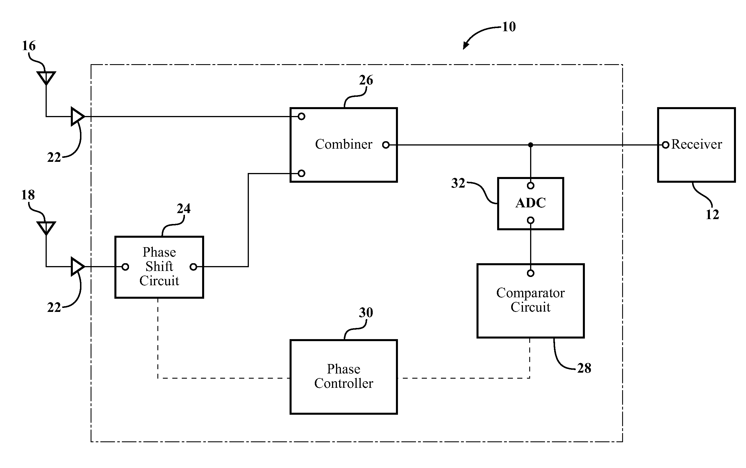
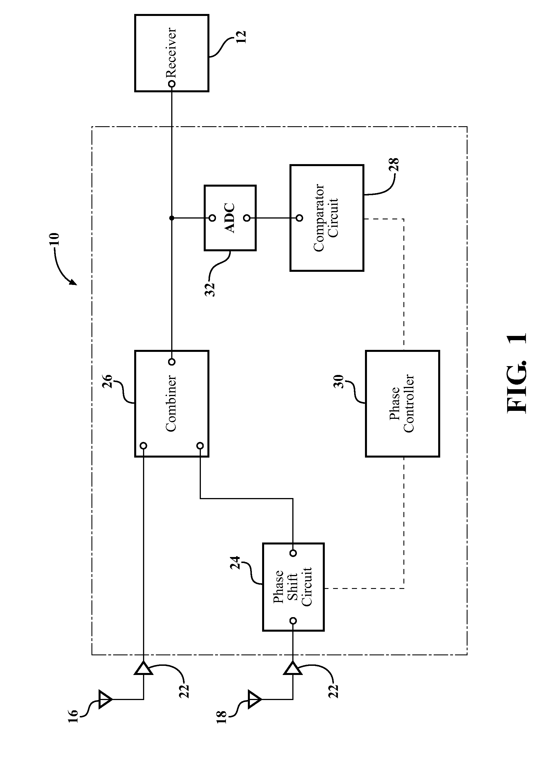
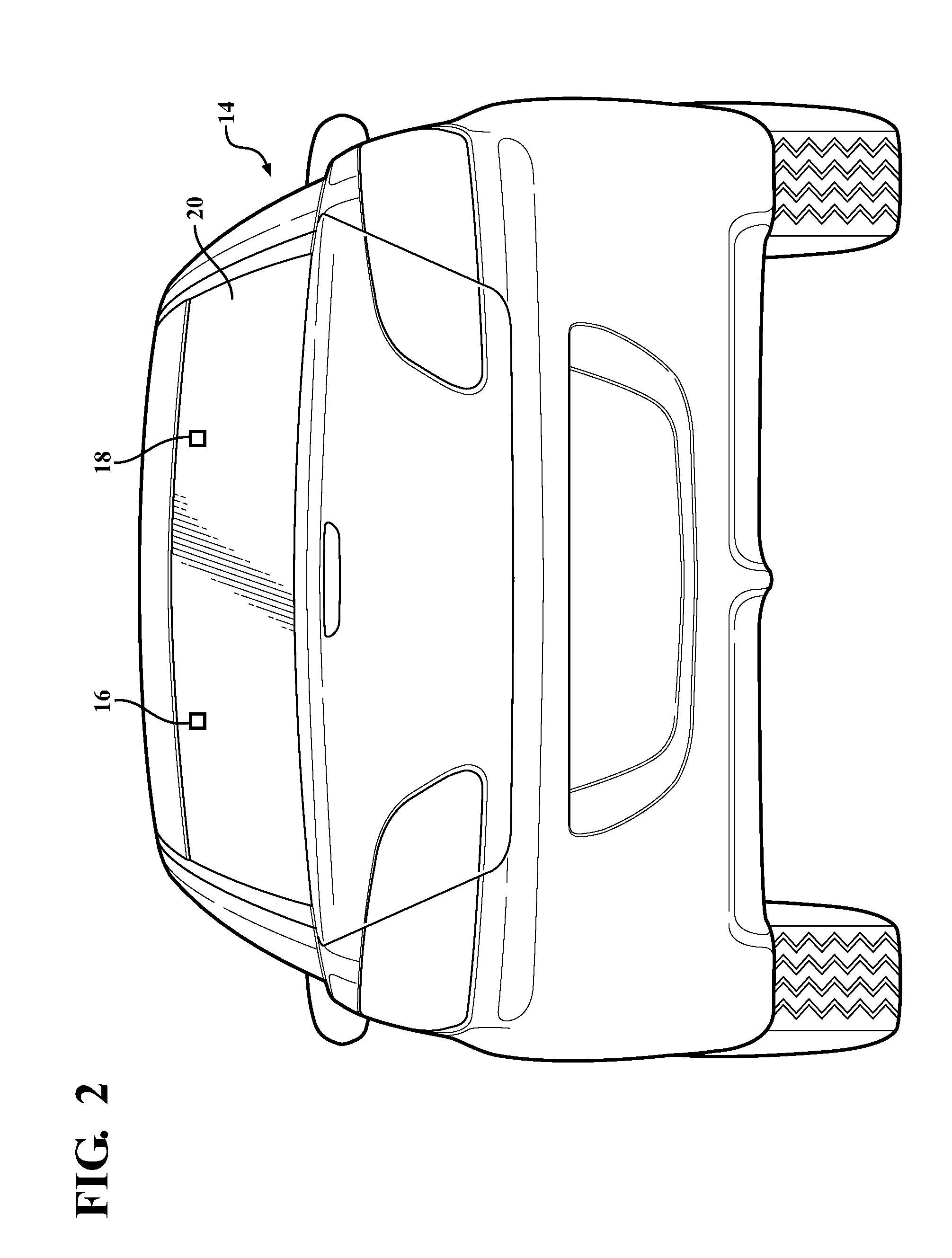
[0014]Referring to the Figures, wherein like numerals indicate like parts throughout the several views, an antenna system 10 for receiving a radio frequency (RF) signal and providing a combined signal to a receiver 12 is shown herein. A method of providing a combined signal to the receiver 12 is also described herein. The system 10 and receiver 12 may be implemented in a vehicle 14. However, those skilled in the art appreciate that the system 10 may be utilized in other non-vehicle applications.

[0015]In the illustrated embodiments, a first antenna 16 and a second antenna 18 each receive the RF signal. That is, each antenna 16, 18 receives the RF signal at a desired frequency or range of frequencies. In the illustrated embodiment, as shown in FIG. 2, the antennas 16, 18 are patch antennas coupled to a single window 20 of the vehicle 14. As such, the antennas 16, 18 are conformal to one another and / or the vehicle 14. However, the system may utilize many different designs and / or types ...


PUM


Abstract

An antenna system for receiving an RF signal from a first antenna and a second antenna includes a phase shift circuit. The phase shift circuit shifts a phase of the RF signal from the second antenna by one of a plurality of possible phase shifts to produce a phase shifted signal. A combiner combines the RF signal from the first antenna and the phase shifted signal to produce a combined signal. A comparator circuit compares a signal quality of the combined signal with a minimum threshold value to determine if the signal quality of the combined signal is equal to or greater than the threshold value. The comparator circuit is in communicative control of the phase shift circuit and maintains the phase shift of the RF signal received by the second antenna in response to the signal quality of the combined signal being equal to or greater than the threshold value.

Description

CROSS REFERENCE TO RELATED APPLICATION[0001]This application claims the benefit of U.S. provisional patent application Nos. 61 / 268,662, 61 / 268,663, 61 / 268,665, 61 / 268,673, 61 / 268,674, and 61 / 268,689, each filed on Jun. 15, 2009 and each of which is hereby incorporated by reference.BACKGROUND OF THE INVENTION[0002]1. Field of the Invention[0003]The application generally relates to a system and method for providing a combined antenna signal to a receiver.[0004]2. Description of the Related Art[0005]The use of radio frequency (RF) receivers in vehicles, such as automobiles, is commonplace. In fact, many vehicles involve multiple RF receivers for different applications. These applications include, but are not limited to, terrestrial AM radio broadcasts, terrestrial FM radio broadcasts, satellite radio broadcast (e.g., SDARS), global positioning system (GPS) reception, and cellular telephone reception.[0006]Typically, vehicles are equipped with a single antenna for each application that ...

Claims


Application Information

Patent Timeline
IPC IPC(8): H04B1/16
CPCH01Q1/1271H01Q1/325H01Q3/2605H01Q3/34H04B7/002H04B17/345H04B7/0857H04B7/086H04B7/10H04B17/0055H04B7/0848
Inventor LEE, MINGVILLARROEL, WLADIMIROLEE, KWAN-HOHORIKI, YASUTAKA
Owner AGC AUTOMOTIVE AMERICAS
Why Eureka
Try Eureka