
Antenna System And Method For Mitigating Multi-Path Effect

a multi-path effect and antenna technology, applied in diversity/multi-antenna systems, transmission monitoring, polarisation/directional diversity, etc., can solve the problems of phasing delay, distorted rf signal received by the antenna and the receiver, and may affect the quality of the signal, so as to mitigate the multi-path effect on the rf signal received, the effect of reducing the phasing delay

Inactive Publication Date: 2010-12-16
AGC AUTOMOTIVE AMERICAS
View PDF98 Cites 5 Cited by
  • Summary
  • Abstract
  • Description
  • Claims
  • Application Information

AI Technical Summary

Benefits of technology

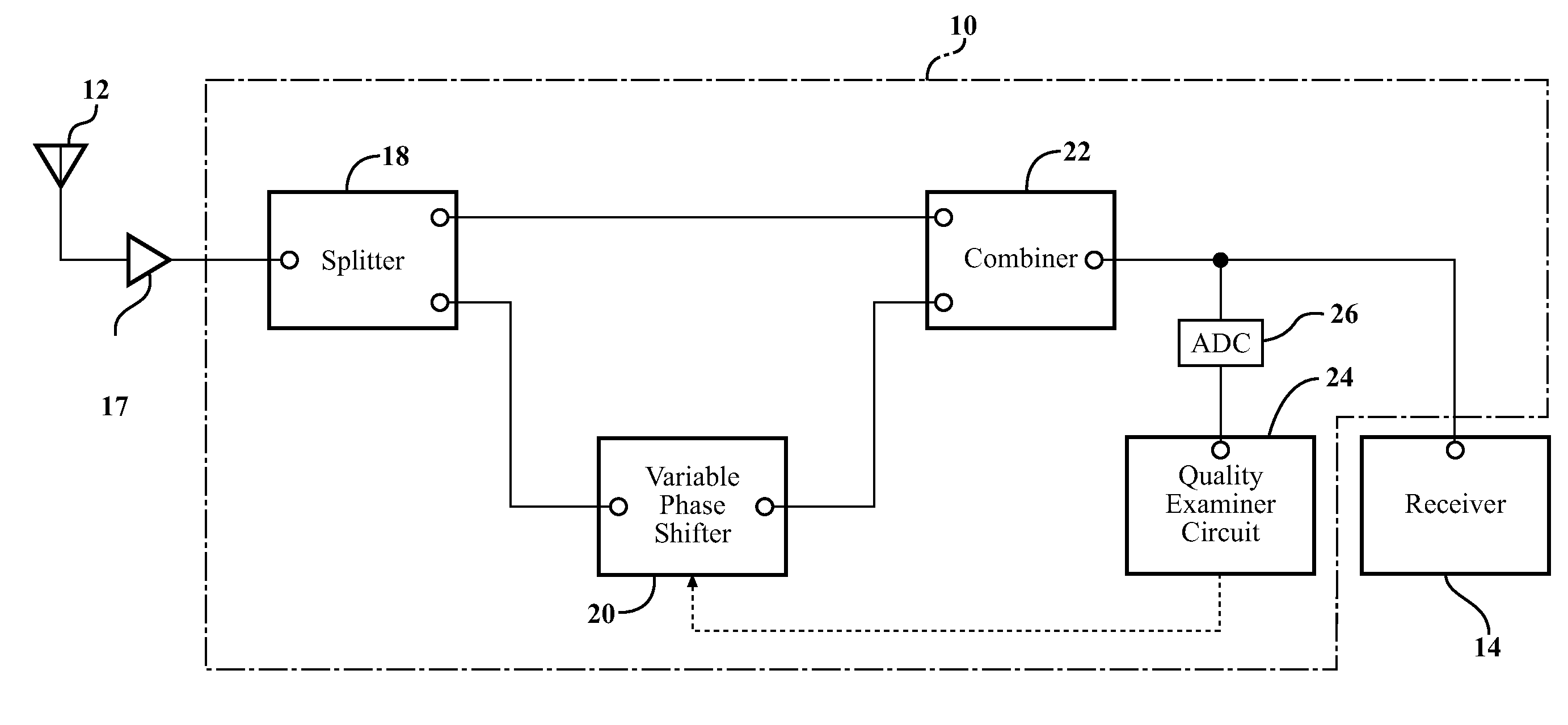
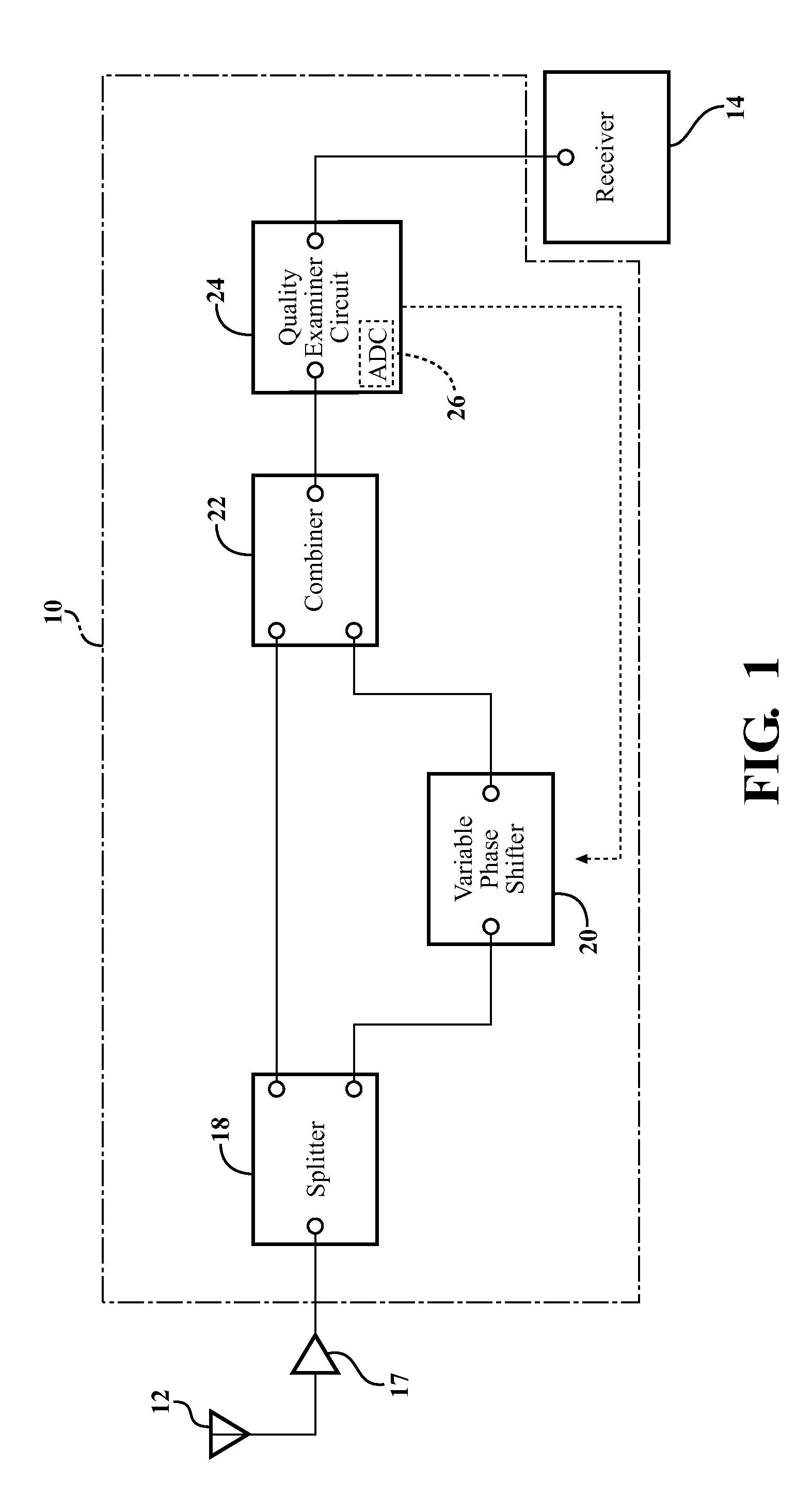
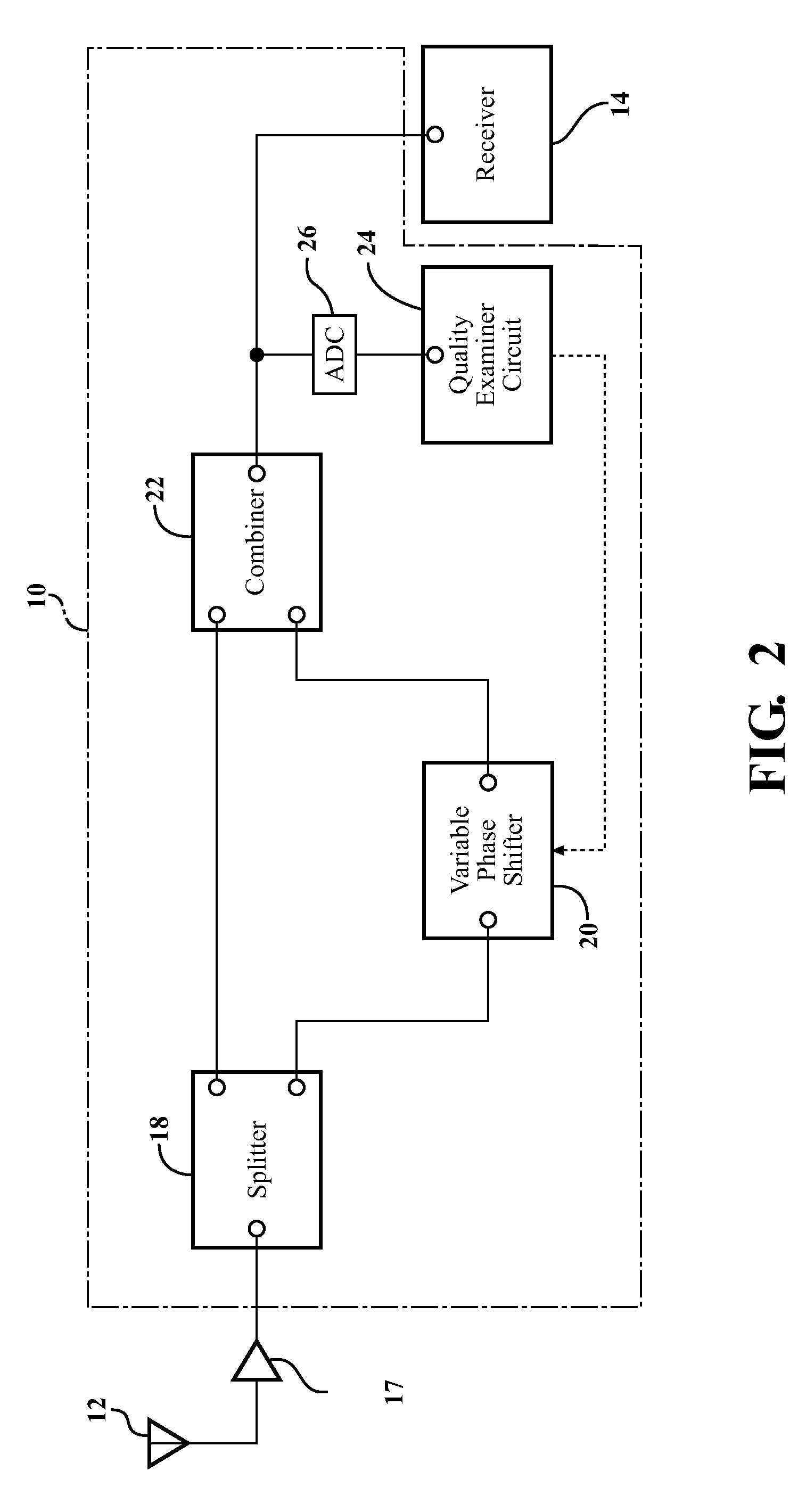
[0008]An antenna system for mitigating a multi-path effect on a radio frequency (RF) signal received by a single antenna is disclosed herein. The system provides a conditioned signal to a receiver. A splitter is electrically connectable to the antenna. The splitter splits the RF signal received by the antenna into a first non-phase shifted signal and a second non-phase shifted signal. A variable phase shifter is electrically connected to the splitter for receiving the second non-phase shifted signal. The phase shifter may phase shift the second non-phase shifted signal to produce a phase shifted signal. The system also includes a combiner having inputs electrically connected to the splitter and the variable phase shifter. The combiner receives and combines the first non-phase shifted signal and the phase shifted signal to produce the conditioned signal. A quality examiner circuit is electrically connected to an output of the combiner. The quality examiner circuit receives the conditioned signal and determines a quality of the conditioned signal. The quality examiner circuit communicates with the variable phase shifter for changing an amount of phase shift of the second non-phase shifted signal based on the quality of the conditioned signal to modify the phase shifted signal to mitigate the multi-path effect on the RF signal received by the antenna.
[0010]By phase-shifting one branch of a split RF signal, then recombining phase shifted and non-phase shifted signals, the system and method mitigate a multi-path effect caused by reflections of the RF signal. The system and method perform well utilizing an input from just a single antenna and without numerous branch circuitry. As such, the system and method provides a cost effective technique to mitigate a multi-path effect on the RF signal especially in comparison to standard antenna diversity schemes.

Problems solved by technology

One challenge in RF signal reception in vehicles is known as the “multi-path effect”.
This effect occurs when an RF signal is reflected off of an object, thus causing a phasing delay.
As such, the RF signal received by the antenna, and by the receiver, may be distorted.

Method used


Image

  • Antenna System And Method For Mitigating Multi-Path Effect
  • Antenna System And Method For Mitigating Multi-Path Effect
  • Antenna System And Method For Mitigating Multi-Path Effect

Examples


first embodiment

[0024]In the system 10, as shown in FIG. 1, the quality examiner circuit 24 includes an input (not numbered) for receiving the conditioned signal and an output (not numbered) electrically connectable to the receiver 14 for providing the modified signal to the receiver 14. As such, the modified signal is passed through the quality examiner circuit 24. The quality examiner circuit 24 may further modify the modified signal with digital signal processing techniques as is realized by those skilled in the art.

second embodiment

[0025]In the system 10, as shown in FIG. 2, the output of the combiner 22 is electrically connectable to the receiver 14 for providing the conditioned signal to the receiver 14. As such, modified signal is not passed through the quality examiner circuit 24, and is not further modified by the quality examiner circuit 24.

[0026]The system 10 may also include an analog-to-digital converter (ADC) 26. The ADC 26 is electrically connected to the combiner 22 and the quality examiner circuit 24 for receiving the conditioned signal from the combiner 22 and providing a digital representation of the conditioned signal to the quality examiner circuit 24. Use of the ADC 26 is especially advantageous when either signal strength or noise are being examined as an aspect of signal quality. In the first embodiment, as shown in FIG. 1, the ADC 26 is integrated with the quality examiner circuit 24. In the second embodiment, as shown in FIG. 2, the ADC 26 is shown separate from the quality examiner circu...


PUM


Abstract

An antenna system and method utilize a splitter electrically connectable to a single antenna for splitting an RF signal into two signals. A variable phase shifter shifts the phase of one of the signals. A combiner combines the phase shifted and non-phase shifted signals to produce a conditioned signal. A quality examiner circuit changes the amount of phase shift provided by the variable phase shifter to produce a plurality of different conditioned signals. The quality examiner circuit then determines a quality of each conditioned signal and changes the phase shift again to provide the highest quality conditioned signal to a receiver.

Description

CROSS REFERENCE TO RELATED APPLICATION[0001]This application claims the benefit of U.S. provisional patent application Nos. 61 / 268,662, 61 / 268,663, 61 / 268,665, 61 / 268,673, 61 / 268,674, and 61 / 268,689, each filed on Jun. 15, 2009 and each of which is hereby incorporated by reference.BACKGROUND OF THE INVENTION[0002]1. Field of the Invention[0003]The application generally relates to a system and method for providing a combined antenna signal to a receiver.[0004]2. Description of the Related Art[0005]The use of radio frequency (RF) receivers in vehicles, such as automobiles, is commonplace. In fact, many vehicles involve multiple RF receivers for different applications. These applications include, but are not limited to, terrestrial AM radio broadcasts, terrestrial FM radio broadcasts, satellite radio broadcast (e.g., SDARS), global position system (GPS) reception, and cellular telephone reception.[0006]One challenge in RF signal reception in vehicles is known as the “multi-path effect”...

Claims


Application Information

Patent Timeline
Patent Type & Authority Applications(United States)
IPC IPC(8): H04B1/10
CPCH01Q1/1271H01Q1/325H01Q3/2605H01Q3/34H04B7/002H04B17/345H04B7/0857H04B7/086H04B7/10H04B17/0055H04B7/0848
Inventor LEE, MINGVILLARROEL, WLADIMIROHORIKI, YASUTAKALEE, KWAN-HO
Owner AGC AUTOMOTIVE AMERICAS
Learn More