
Spectral endoscope and its wavelength calibration method

a technology of spectral endoscope and wavelength calibration method, which is applied in the field of spectral endoscope and its wavelength calibration method, can solve the problem that the image of light in a desired wavelength band cannot be performed

Inactive Publication Date: 2010-12-16
OLYMPUS CORP
View PDF8 Cites 71 Cited by
  • Summary
  • Abstract
  • Description
  • Claims
  • Application Information

AI Technical Summary

Benefits of technology

[0024]The present invention demonstrates an effect in which the spectral characteristic can be precisely set to be suitable for use conditions of the spectral endoscope.

Problems solved by technology

Because of this, inconveniently, imaging of light in a desired wavelength band can not be performed.

Method used


Image

  • Spectral endoscope and its wavelength calibration method
  • Spectral endoscope and its wavelength calibration method
  • Spectral endoscope and its wavelength calibration method

Examples


Embodiment Construction

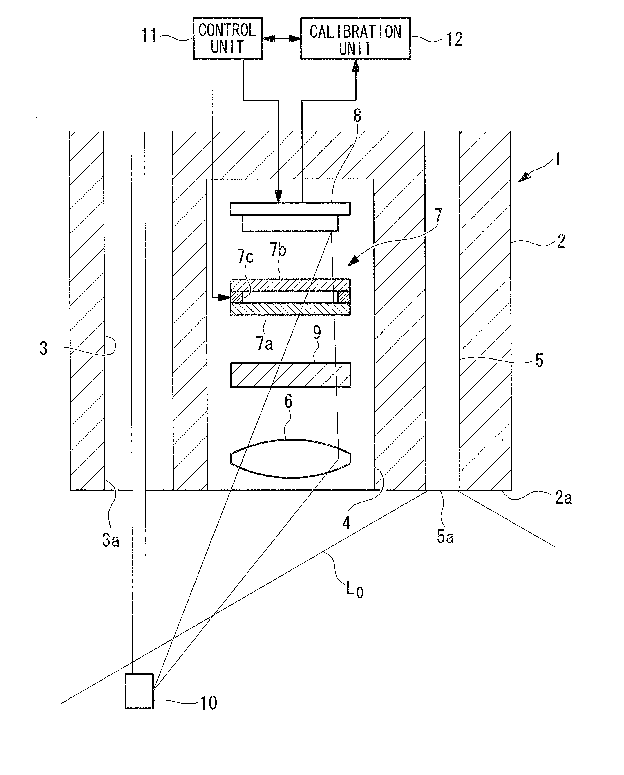
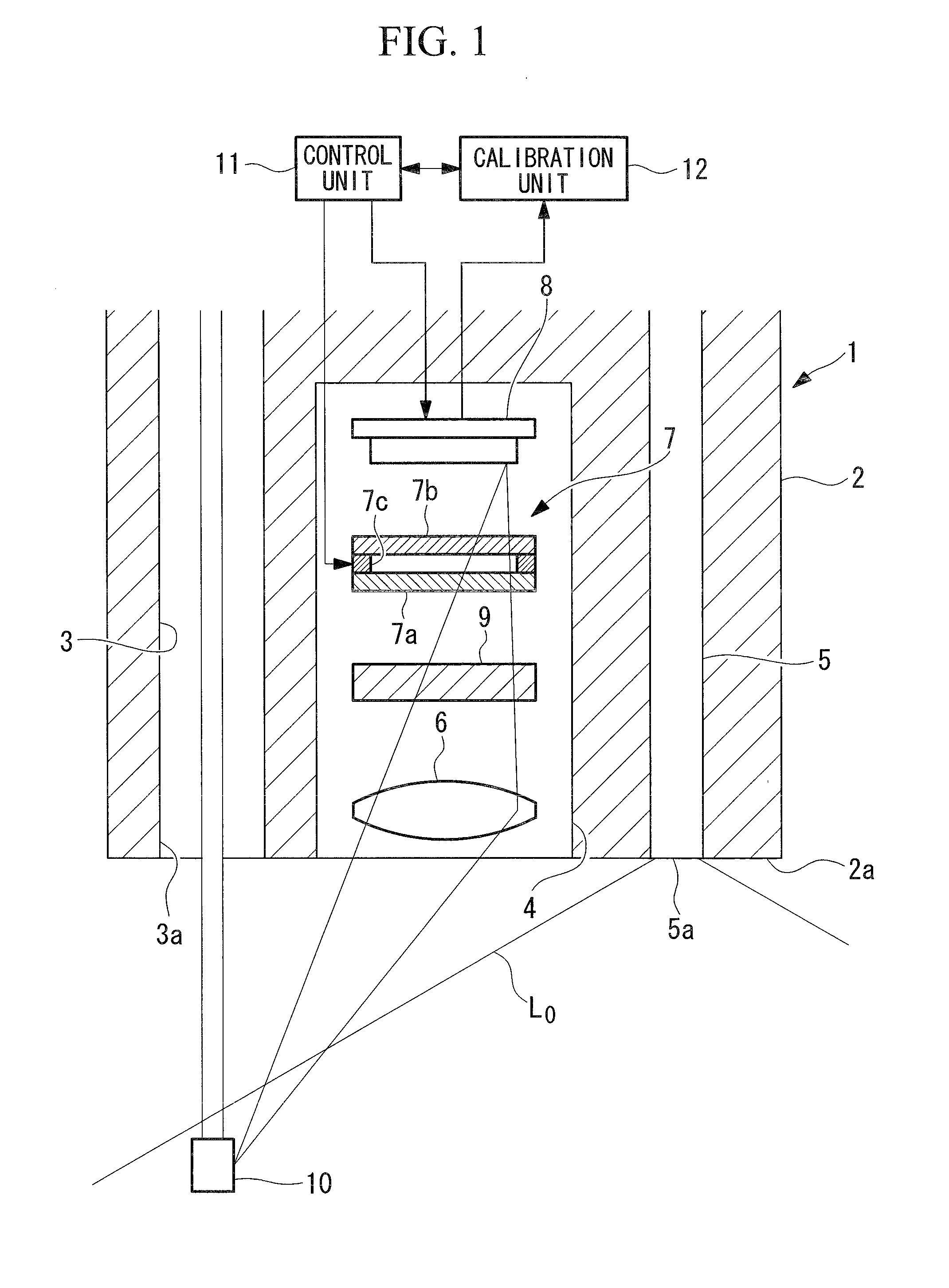
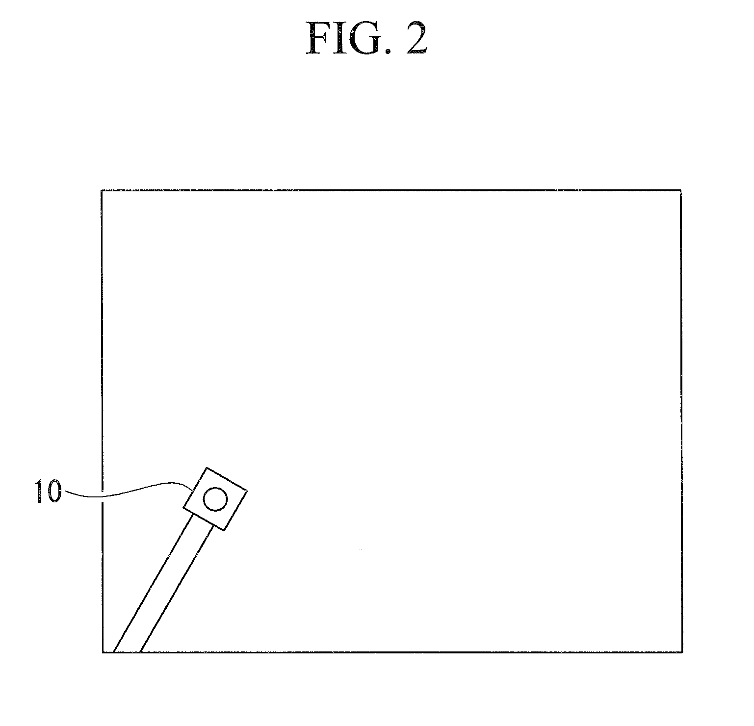
[0038]Hereunder is a description of a spectral endoscope 1 and its wavelength calibration method according to one embodiment of the present invention, with reference to FIG. 1 to FIG. 5.

[0039]As shown in FIG. 1, the spectral endoscope 1 to which the wavelength calibration method according to this embodiment is applied, comprises a long and slender insertion unit 2 to be inserted into a body cavity of the patient. In the insertion unit 2 is arranged a forceps channel (channel) 3 for insertion of treatment tools such as forceps, along an approximately all over the longitudinal direction of the insertion unit 2.

[0040]In addition, on the distal end of the insertion unit 2 are arranged one end faces of an imaging unit 4 and a light guide (excitation light emission unit) 5 which emits excitation light L0.

[0041]The imaging unit 4 comprises an object lens 6 which converges light incident from the forward area beyond the distal end face 2a of the insertion unit 2, a variable spectral device ...


PUM


Abstract

When using a spectral endoscope, the spectral characteristic can be precisely set to be suitable for use conditions. There is provided a spectral endoscope (1) comprising: a channel (3) arranged along a longitudinal direction in an insertion unit to be inserted into a body cavity; an image pickup section (8) which captures an image in a vicinity of the distal end of the insertion unit (2); a variable spectral section (7) capable of changing the wavelength of light to be incident into the image pickup section (8); a reference light member (10) which emits light of a known wavelength characteristic, or has a known absorption characteristic, and is to be introduced into a field-of-view range of the image pickup section (8) through the channel (3); a control unit (11) which controls the image pickup section (8) to capture an image of the reference light member (10) that has been introduced through the channel (3), while controlling the variable spectral section (7) to change the wavelength of light to be incident into the image pickup section (8); and a calibration unit (12) which calibrates the spectral characteristic of the variable spectral section (7) according to the image of the reference light member (10) that has been captured by the image pickup section (8).

Description

TECHNICAL FIELD[0001]The present invention relates to a spectral endoscope and its wavelength calibration method.BACKGROUND ART[0002]Conventionally, there is known a Fabry-Perot type variable spectral device which changes the face-to-face spacing between two planar optical substrates so as to change the wavelength of light to be transmitted therethrough (for example, refer to Patent Document 1).[0003]This variable spectral device comprises reflection films and capacitance sensor electrodes on opposite surfaces of the respective optical substrates, so that the spacing dimension between the optical substrates is detected based on the capacitance value between the capacitance sensor electrodes, and the spacing between the optical substrates is changed by driving actuators to change the wavelength of light to be transmitted therethrough.[0004]In addition, conventionally, there is also known a spectral endoscope comprising, in the distal end thereof, a built-in Fabry-Perot type variable ...

Claims


Application Information

Patent Timeline
IPC IPC(8): A61B1/04
CPCA61B1/00057A61B1/045A61B1/043
Inventor TAKAOKA, HIDEYUKIMATSUMOTO, SHINYA
Owner OLYMPUS CORP
Learn More