Heat exchanger for cooling high-temperature gas
- Summary
- Abstract
- Description
- Claims
- Application Information
AI Technical Summary
Benefits of technology
Problems solved by technology
Method used
Image
Examples
first embodiment
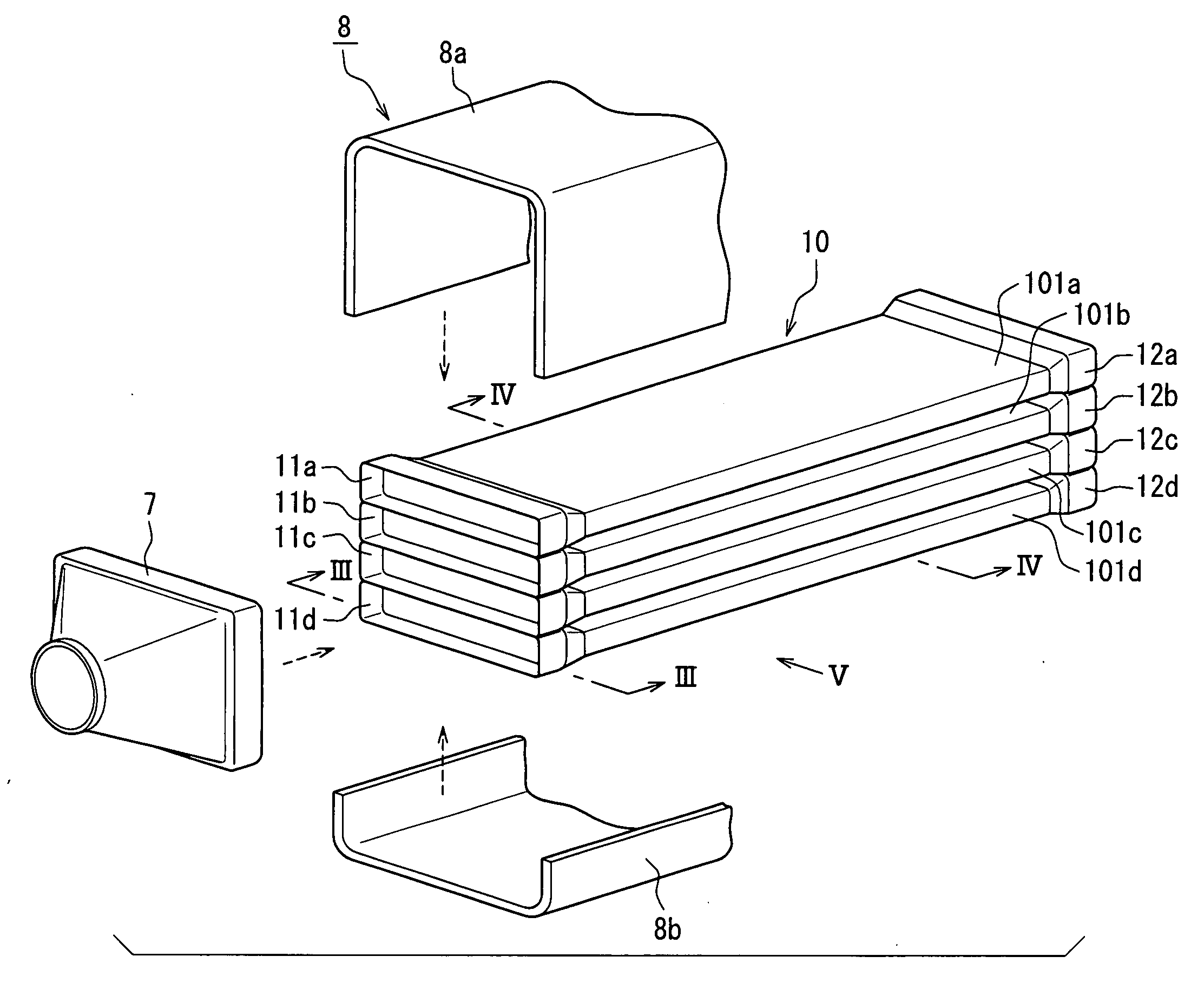
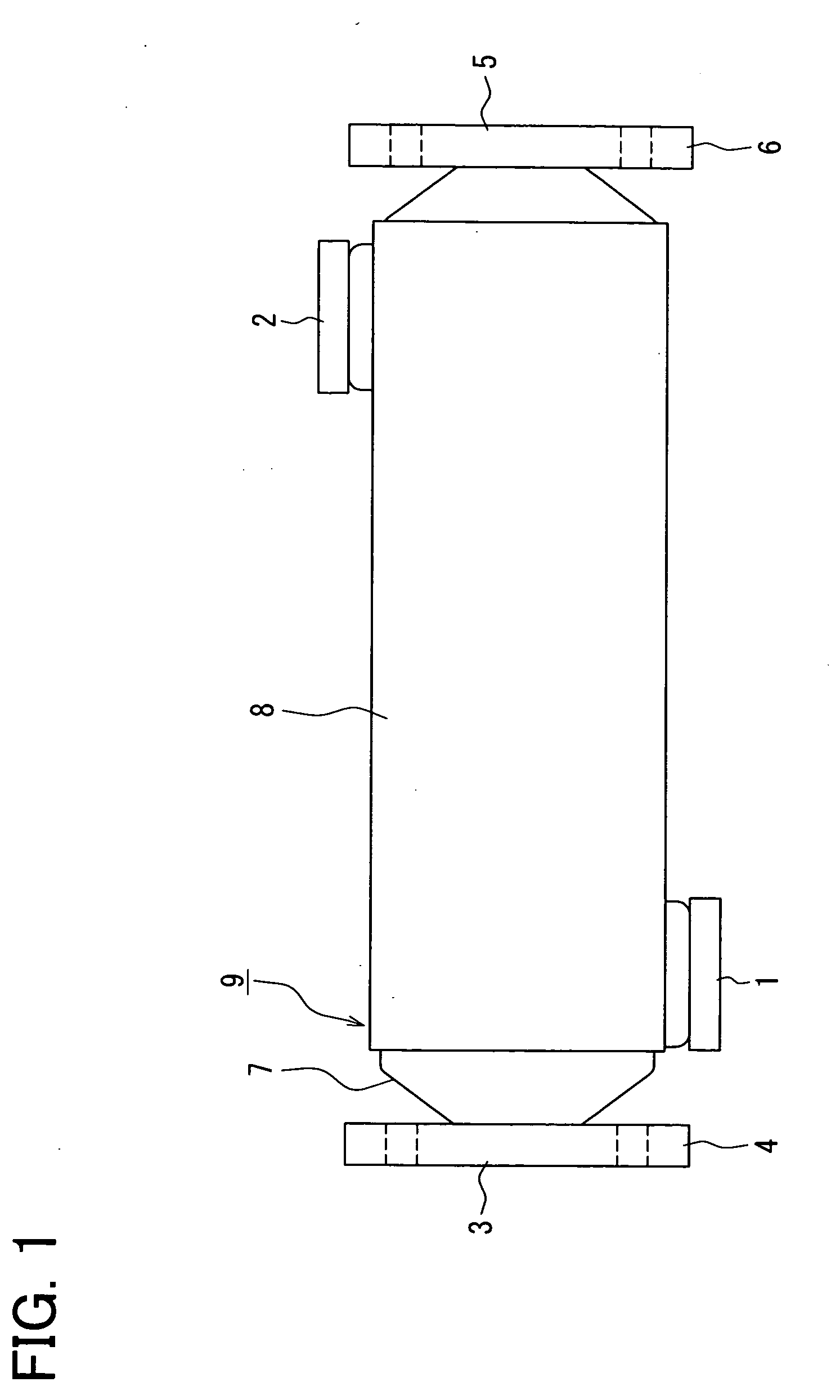
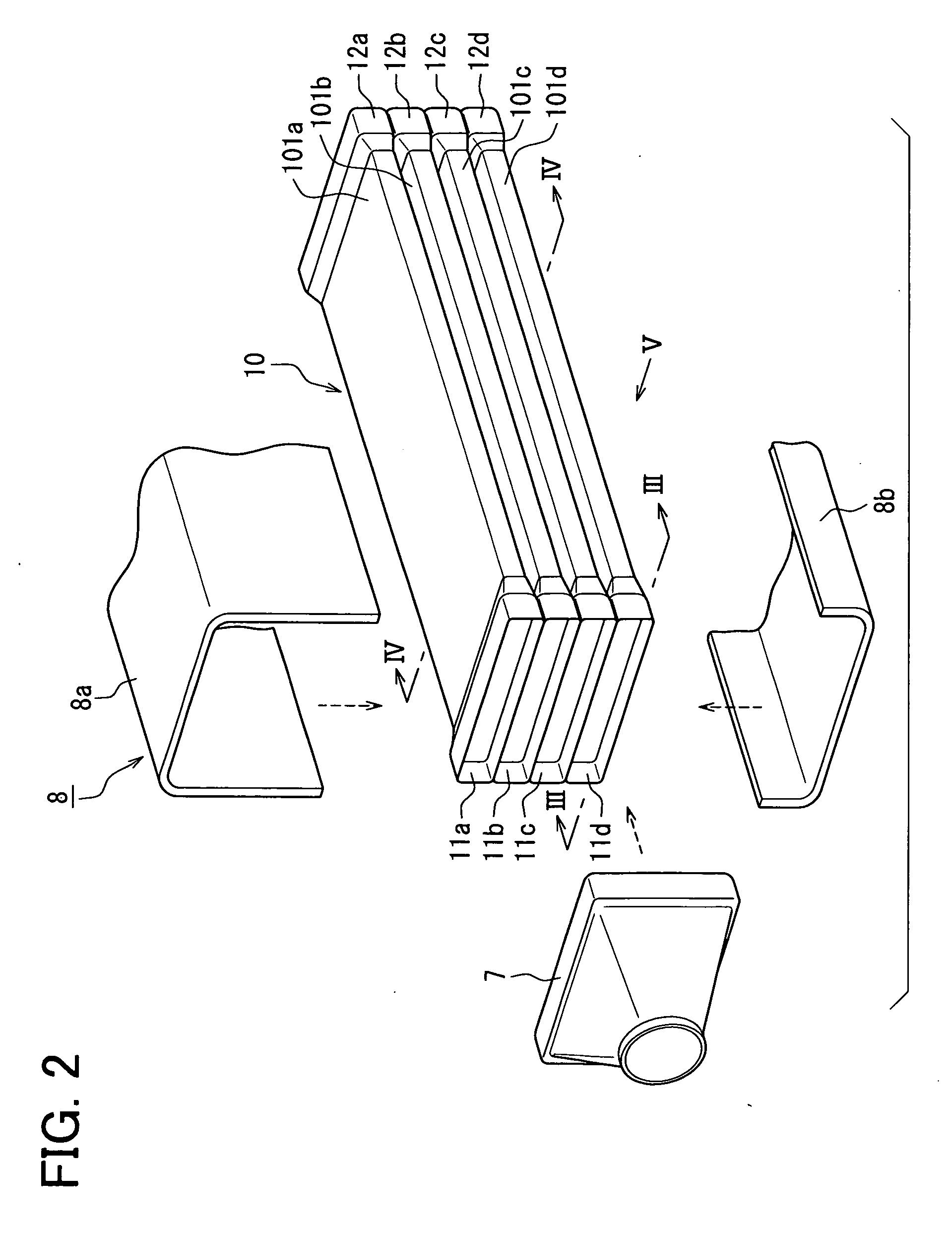
[0029]Hereafter, a first embodiment of the present invention will be described with reference to FIGS. 1 to 8. FIG. 1 is an outline view showing an EGR heat exchanger as a heat exchanger for cooling high-temperature gas of the present embodiment. In FIG. 1, the reference numeral 1 indicates an inlet port of water which serves as a cooling medium. A coolant at approximately 90° C. flows from the inlet port 1.
[0030]The reference numeral 2 indicates an outlet port of water. The reference numeral 3 indicates an inlet port of high-temperature exhaust gas, and an inlet-side flange 4 is attached to the periphery of the inlet port 3. The reference numeral 5 indicates an outlet port of high-temperature exhaust gas, and an outlet-side flange 6 is attached to the periphery of the outlet port 5. The reference numerals 7 and 8 indicate a gas tank portion and a cooling-medium tank portion (hereinafter, also referred to as a water tank portion), respectively.
[0031]A joint portion 9 (also referred ...
second embodiment
[0053]Next, a second embodiment of the present invention will be described. FIG. 9 is a cross-sectional view showing a partition portion according to the second embodiment of the present invention. In the following embodiments, similar components to those in the first embodiment are indicated by the same reference numerals, and descriptions thereof will not be repeated. In the following embodiments, different configurations from those in the first embodiment will be described.
[0054]As with the first embodiment, the joint portion 9 is formed by stacking the gas tank portion 7, the water tank portion 8, and the tube 10, as shown in FIG. 9. An end portion of the gas tank portion 7 is projected to a side of the cooling medium in the gap 15 to form a projecting portion 7a. Since the gas tank portion 7 can be efficiently cooled by forming the projecting portion 7a, an alleviation effect of the temperature gradient can be increased.
third embodiment
[0055]Next, a third embodiment of the present invention will be described. FIG. 10 is a cross-sectional view showing a partition portion according to the third embodiment of the present invention. In the present embodiment, different configurations from those in the above-described embodiments will be described. In the third embodiment, as shown in FIG. 10, a baffle 20 is further placed at a side of the gas tank portion 7 of the joint portion 9 so that the high-temperature gas is not blown directly toward the joint portion 9. By placing the baffle 20, a flow rate of a part of the high-temperature gas is decreased, and the temperature gradient of the joint portion 9 is alleviated.
PUM
 Abstract
Description
Claims
Application Information
 - R&D
- Intellectual Property
- Life Sciences
- Materials
- Tech Scout
- Unparalleled Data Quality
- Higher Quality Content
- 60% Fewer Hallucinations
Browse by: Latest US Patents, China's latest patents, Technical Efficacy Thesaurus, Application Domain, Technology Topic, Popular Technical Reports.
© 2025 PatSnap. All rights reserved.Legal|Privacy policy|Modern Slavery Act Transparency Statement|Sitemap|About US| Contact US: help@patsnap.com


