Heat Exchange Assembly and Method

Inactive Publication Date: 2010-12-23
STSS
View PDF11 Cites 4 Cited by
  • Summary
  • Abstract
  • Description
  • Claims
  • Application Information

AI Technical Summary

Benefits of technology

[0010]PEX tubing is slightly less efficient at conducting heat than copper tubing at the operating temperature of the heat exchanger, but is much cheaper and lighter than copper tubing. PEX tubing can be hand coiled quickly without the need for an expensive winding machine. The smaller amount of copper can be wound in a few minutes. PEX tubing is manufactured as straight pipe and is easily coiled. A frame or cage surrounds the PEX tubing coil to force the PEX tubing coil to maintain its cylindrical, vertical spiral shape.
[0012]The mixture of copper and PEX tubing reduces the weight of the heat exchanger, reducing the cost of transportation and simplifying the installation procedure.

Problems solved by technology

This makes the tubes expensive to produce due to raw material and manufacturing costs.
Traditional coils are heavy, increasing transportation costs and installation difficulty.

Method used


Image

  • Heat Exchange Assembly and Method
  • Heat Exchange Assembly and Method
  • Heat Exchange Assembly and Method

Examples


Embodiment Construction

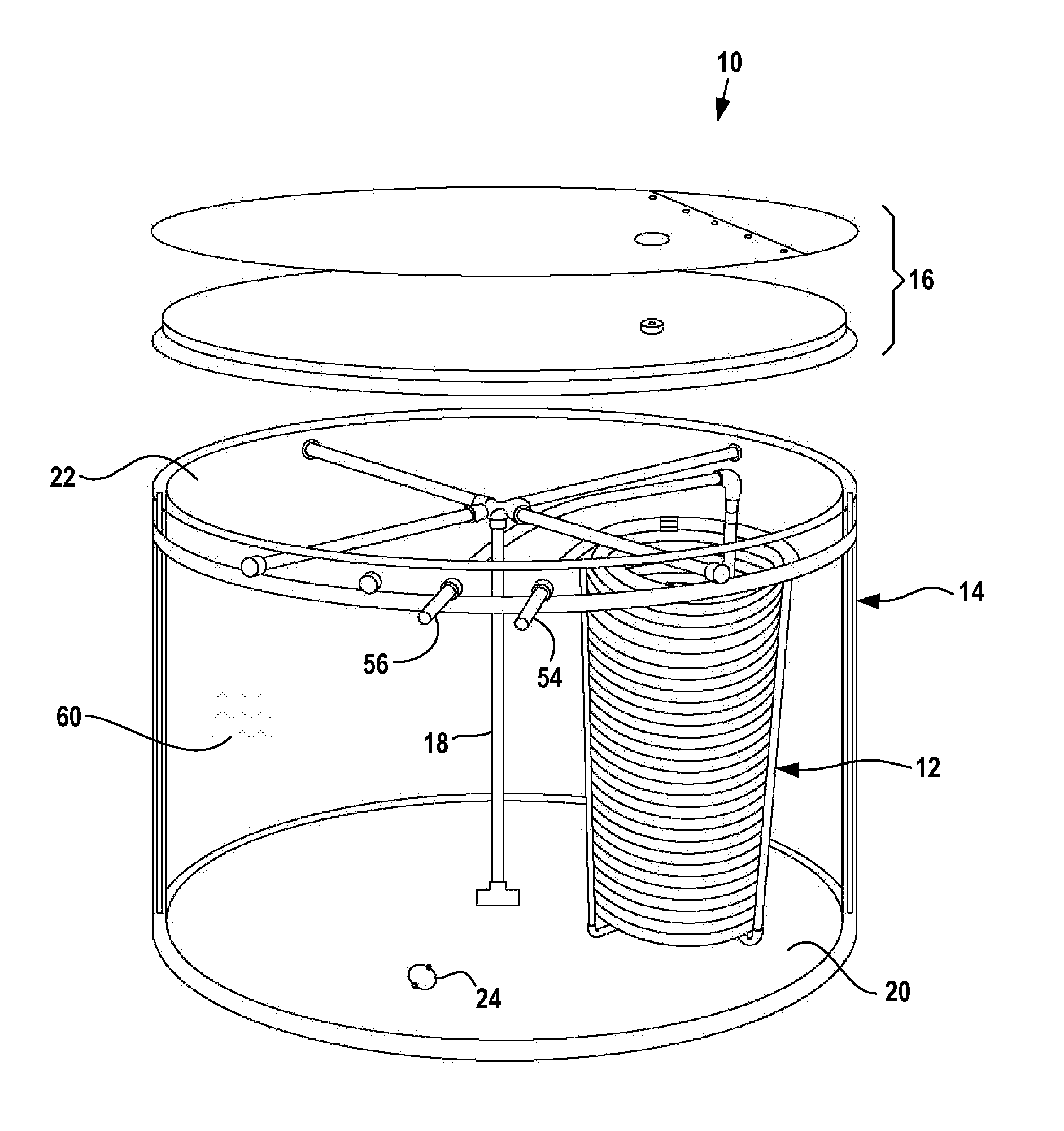
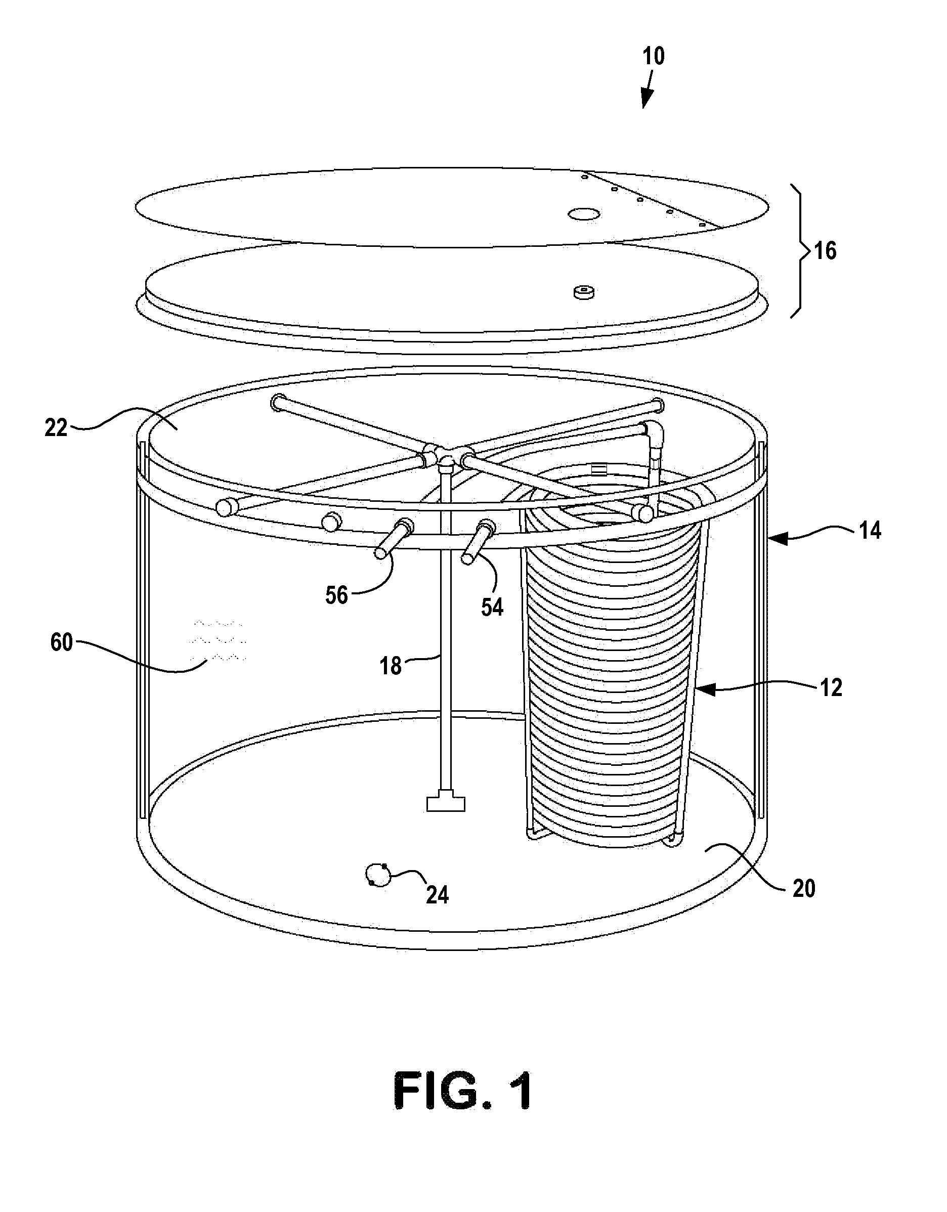
[0021]Heat exchange assembly 10 includes heat exchanger 12 installed in tank 14. Tank 14 may be a conventional insulated water tank having a lid 16 and a brace 18. Brace 18 supports lid 16 when the lid is placed on the tank. Brace 18 extends upward from tank bottom 20 to tank top 22. Drain 24 is located at tank bottom 20 to allow draining tank 14.

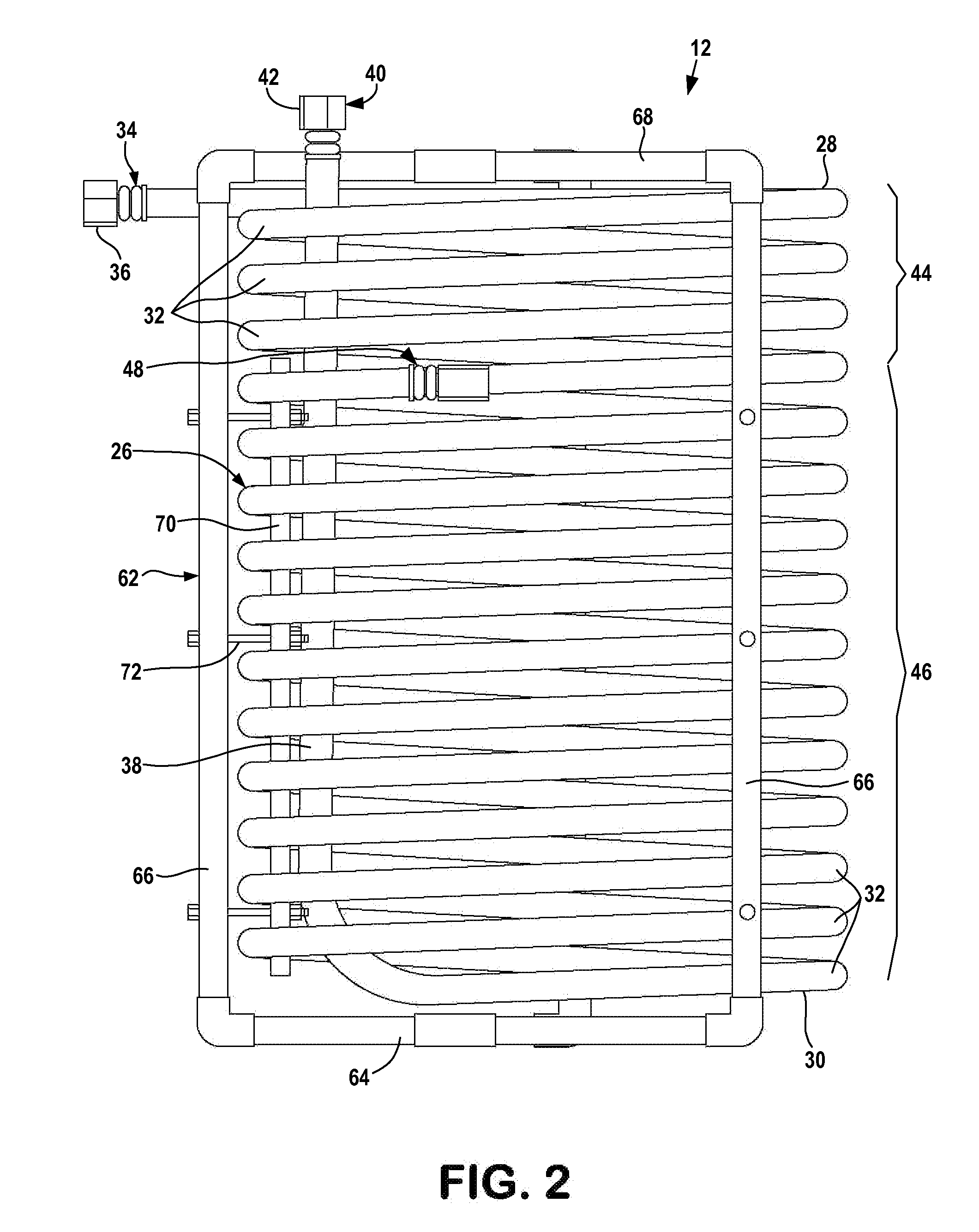
[0022]Heat exchanger 12 is made up of an elongate coiled tube 26 extending generally axially from exchanger top 28 to exchanger bottom 30. Tube 26 forms a number of circular coiled loops 32 that extend from exchanger top 28 to exchanger bottom 30. Tube first end 34 is located at exchanger top 28 and includes a fitting 36. Fitting 36 may be a conventional female pipe threading. The bottom coiled loop 32 of tube 26 is joined to vertical output line 38. Output line 38 extends up through the center of the exchanger beyond exchanger top 28 to a tube second end 40. Tube second end 40 includes a fitting 42 which may be conventional female pipe thr...


PUM

PropertyMeasurementUnit
Fractionaaaaaaaaaa
Fractionaaaaaaaaaa
Flow rateaaaaaaaaaa

Abstract

A heat exchanger assembly of the type having a cylindrical coil in an insulated tank, the assembly having different heat exchanger sections having different thermal conductivities.

Description

FIELD OF THE INVENTION[0001]The invention relates to heat exchange assemblies, particularly assemblies used to transfer heat to and from a water tank.BACKGROUND OF THE INVENTION[0002]Heat exchange assemblies are commonly used to heat water and then extract heat from the water.[0003]Solar energy systems include a solar heat exchanger that heats a liquid that is flowed through a heat exchange assembly positioned in a large body of water in an insulated tank. The solar heated water flows through the heat exchange assembly to heat the water in the tank. Heated water stores solar energy that may be extracted from the heated water by the heat exchange assembly to heat liquid flowing through the assembly. The heated liquid may be used to heat domestic hot water, to heat the interior of a building or otherwise.[0004]In a conventional heat exchange assembly used to heat or cool a body of water, a heat exchange liquid flows though a vertically coiled tube immersed in the water. The coiled tub...

Claims


Application Information

Patent Timeline
IPC IPC(8): F28D7/02
CPCF28D7/024F28D20/0034Y02E60/142F28F21/062F28F21/08F28F9/26Y02E60/14
Inventor TJERNAGEL, SVEN L.
Owner STSS
Why Eureka
Try Eureka