
Method and device for heating stator

Active Publication Date: 2010-12-23
TOYOTA JIDOSHA KK
View PDF3 Cites 18 Cited by
  • Summary
  • Abstract
  • Description
  • Claims
  • Application Information

AI Technical Summary

Benefits of technology

[0012]Therefore, the applicants studied a technique in which high-frequency induction heating coils are disposed near coil end parts at both ends of a stator respectively to allow a large amount of high-frequency magnetic flux to pass through the coil end parts, thereby preventing local heating of the core outer peripheral end portions, and enabling uniform heating of the stator.

Problems solved by technology

However, the technique studied by the applicants would be insufficient to achieve the purpose of efficiently heating the stator.

Method used


Image

  • Method and device for heating stator
  • Method and device for heating stator
  • Method and device for heating stator

Examples


Embodiment Construction

[0054]A detailed description of a preferred embodiment of the present invention will now be given referring to the accompanying drawings.

[0055]Firstly, a heating method and a configuration of heating device of the present embodiment will be explained briefly and schematically.

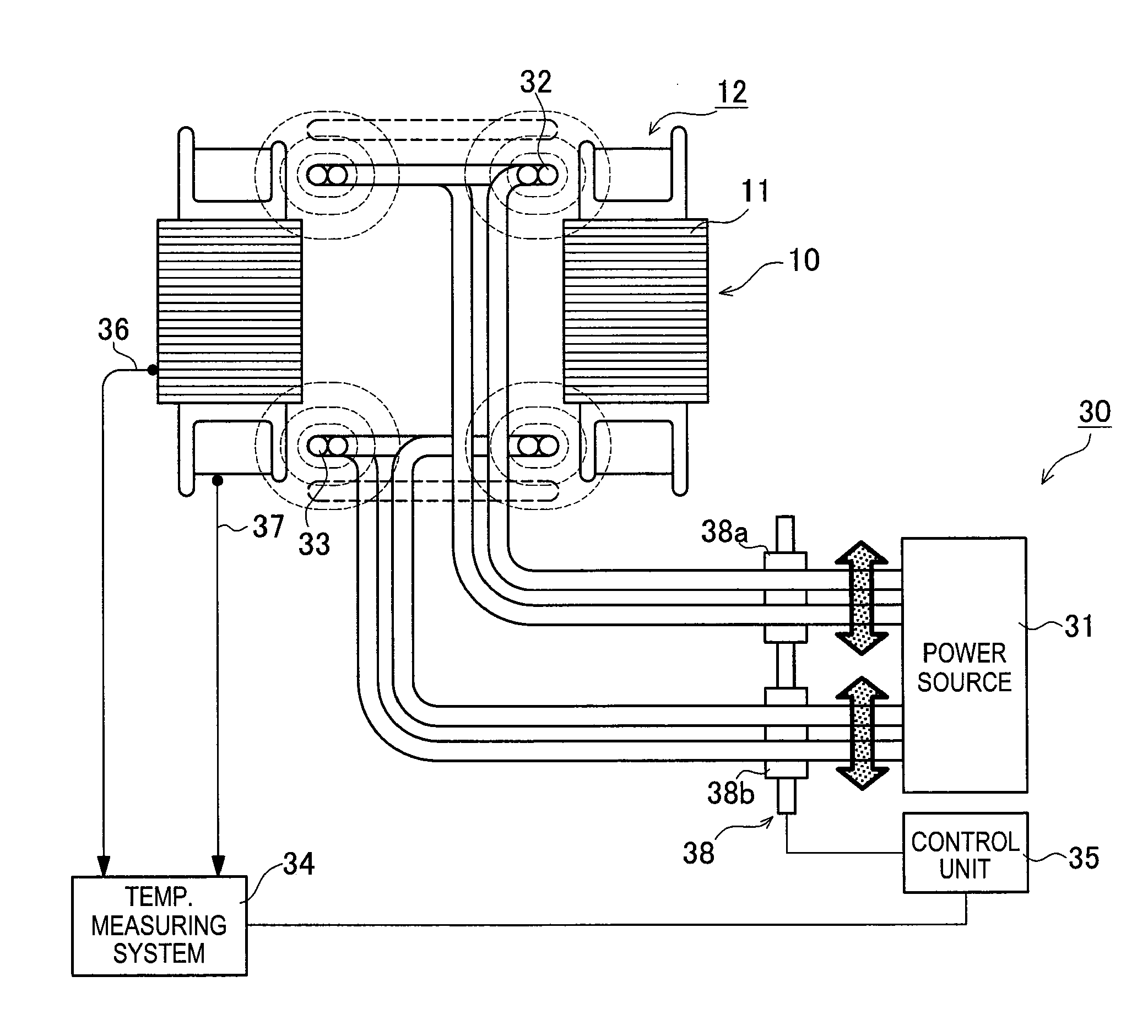
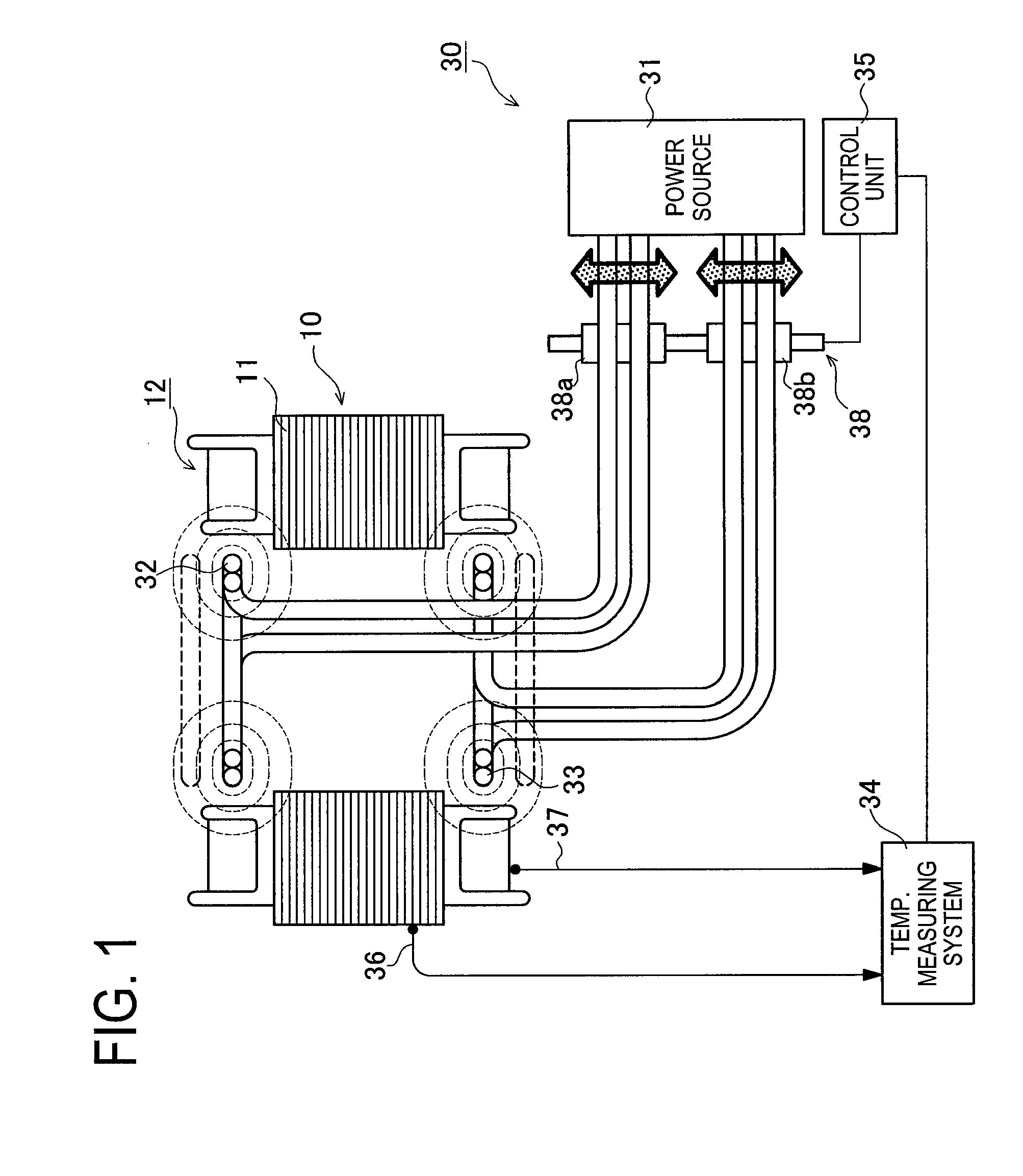
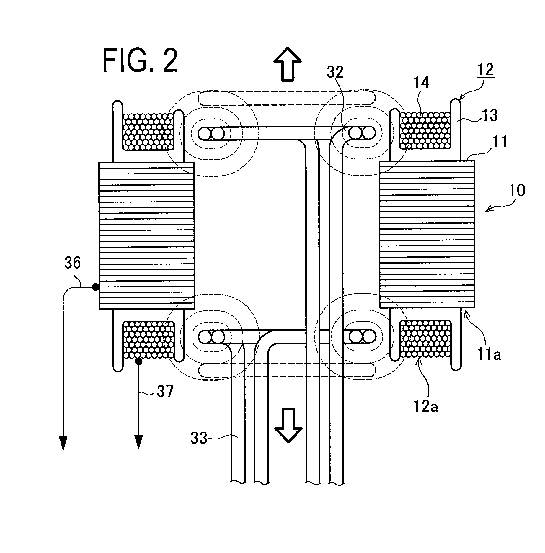
[0056]FIG. 1 is a schematic view of a heating device 30 of the present embodiment. FIG. 2 is an enlarged cross-sectional view of a stator 10 and its surrounding in FIG. 1.

[0057]The heating device 30 includes a power source 31, a first induction coil 32, a second induction coil 33, and a temperature measuring system 34.

[0058]The power source 31 generates an alternating current to supply power to the first induction coil 32 and a second induction coil 33. Each of the first induction coil 32 and the second induction coil 33 is formed of a hollow pipe having a diameter of about 10 mm and a circularly wound form. The hollow pipe is made of a high-conductive material such as copper and designed to allow cooling water...


PUM


Abstract

In a method of heating a stator, a first induction coil is disposed near one of the coil ends of the stator, and a second induction coil is disposed near the other, and the first induction coil and the second induction coil are electrically energized, whereby the induction-heating of the stator is performed as a pre-heating step prior to the resin molding step of the coil ends. According to this method, a first movement unit for moving the first induction coil and a second movement unit for moving the second induction coil are provided, the first induction coil is moved by the first movement unit and the second induction coil is moved by the second movement unit for induction-heating of the stator.

Description

TECHNICAL FIELD[0001]The present invention relates to a technique for uniformly heating a coil end part and a stator core of a stator of a motor in order to subject them to pre-heating, annealing process, and others.BACKGROUND ART[0002]A stator to be used in a motor has a core end part insulated and protected by a varnish impregnating method in which varnish is impregnated between wire cores each being wound on a stator core and then the varnish is heated to be solidified or by a resin-molding method in which the core end part of the stator is injection-molded with resin by use of a die to fill insulating resin between wire cores.[0003]As the method of impregnating varnish between the wire cores, there are known an impregnating method conducted by dropping varnish while rotating the stator and a dipping method conducted by dipping a lower part of each wire coil in a varnish bath to impregnate varnish by capillary phenomenon.[0004]Both cases need, before and after a molding process, ...

Claims


Application Information

Patent Timeline
IPC IPC(8): H05B6/10
CPCH02K15/12
Inventor KOIDE, SATOSHIKIMURA, HIDEAKISAKAO, MASAHIKO
Owner TOYOTA JIDOSHA KK
Learn More