Two-level clamp for photovoltaic modules

a photovoltaic module and clamping technology, applied in the field of clamping for inclined attachment of rectangular photovoltaic modules, can solve the problems of above-mentioned damage to the clamp, and achieve the effects of reducing the efficiency of the entire module, reducing friction coefficient, and highest electrical resistan

Inactive Publication Date: 2010-12-23
ADENSIS
View PDF9 Cites 15 Cited by
  • Summary
  • Abstract
  • Description
  • Claims
  • Application Information

AI Technical Summary

Benefits of technology

[0011]According to an embodiment, the first and the second deposit or supporting surface, point or line, when projected onto the bottom side (and hence in the installed state also onto the module rail), are spaced from one another, so that the higher edge of the first deposit or supporting surface (point, line) has a predetermined distance to the lower edge of the second deposit or supporting surface (point, line). With this approach, even for a low positions of the sun, for example during the winter, the lower edge of the second photovoltaic module is advantageously not shadowed by the upper edge of the first PV module. Such shadowing significantly reduces the efficiency of the entire module, because the individual photovoltaic cells of the module are connected in series and the cell with the weakest incident radiation exhibits the highest electrical resistance.
[0012]The distance mentioned in the previous section produces a region on the base which is unobstructed from above, with neither the first nor the second supporting surface impeding its accessibility. The surface area of this region is defined by the predetermined spacing, and the base includes in this region a hole through which a screw, rivet or the like passes, with which the clamp is attached on the module rail. Advantageously, the center portion of the bracket may also include an opening, which is aligned with the hole of the clamp in the installed state. A single screw is sufficient to affix the clamp on the module rail. In thi

Problems solved by technology

By configuring the clamp with supports that are open towards the top, in particular flat, identically inclined supporting surfaces or supports with a spherical top surface, which each provide a supporting point, or supports with a curved cylindric

Method used


Image

  • Two-level clamp for photovoltaic modules
  • Two-level clamp for photovoltaic modules
  • Two-level clamp for photovoltaic modules

Examples


Embodiment Construction

[0021]Throughout the Figures, same or corresponding elements are generally indicated by same reference numerals. These depicted embodiments are to be understood as illustrative of the invention and not as limiting in any way. It should also be understood that the drawings are not necessarily to scale and that the embodiments are sometimes illustrated by graphic symbols, phantom lines, diagrammatic representations and fragmentary views. In certain instances, details which are not necessary for an understanding of the present invention or which render other details difficult to perceive may have been omitted.

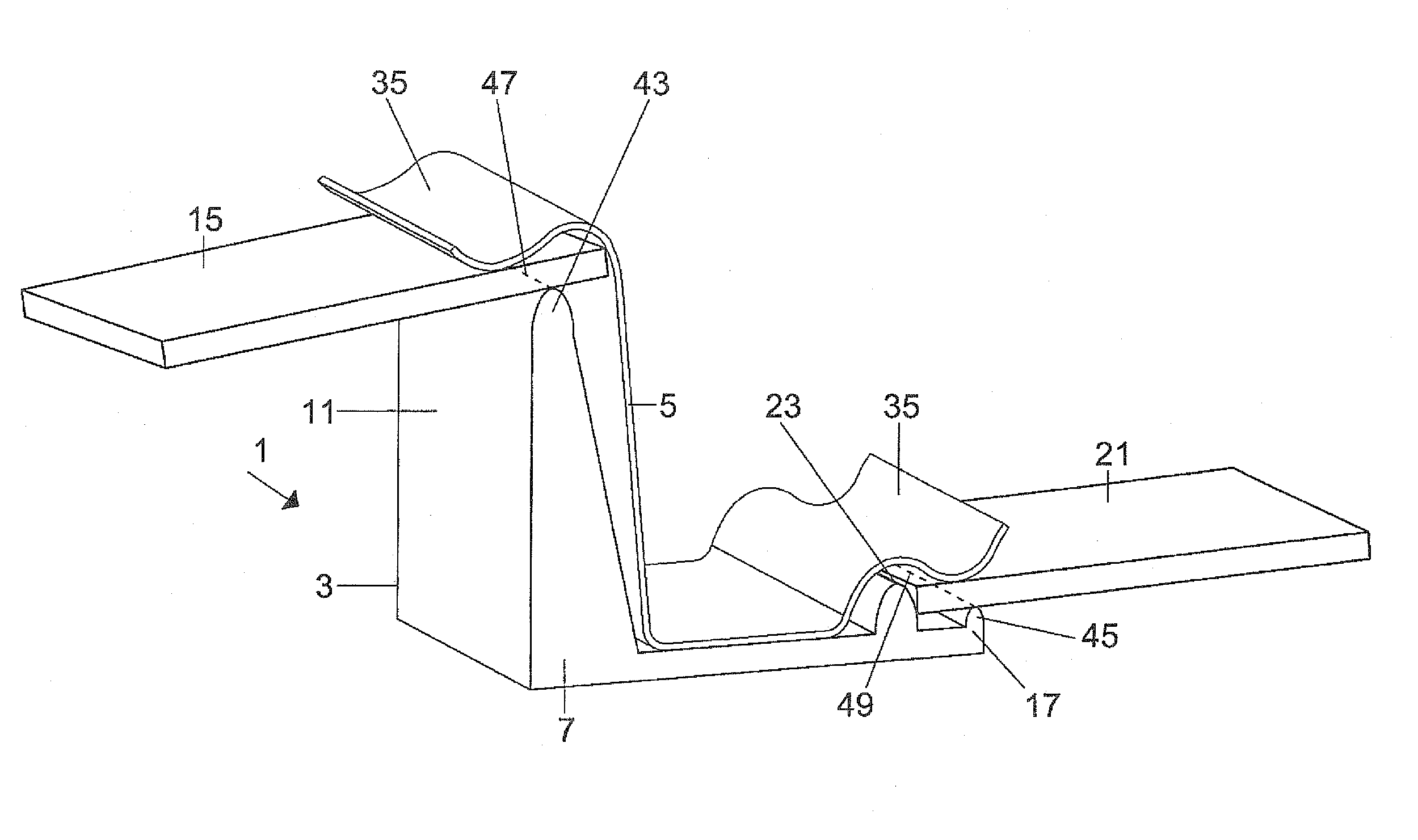
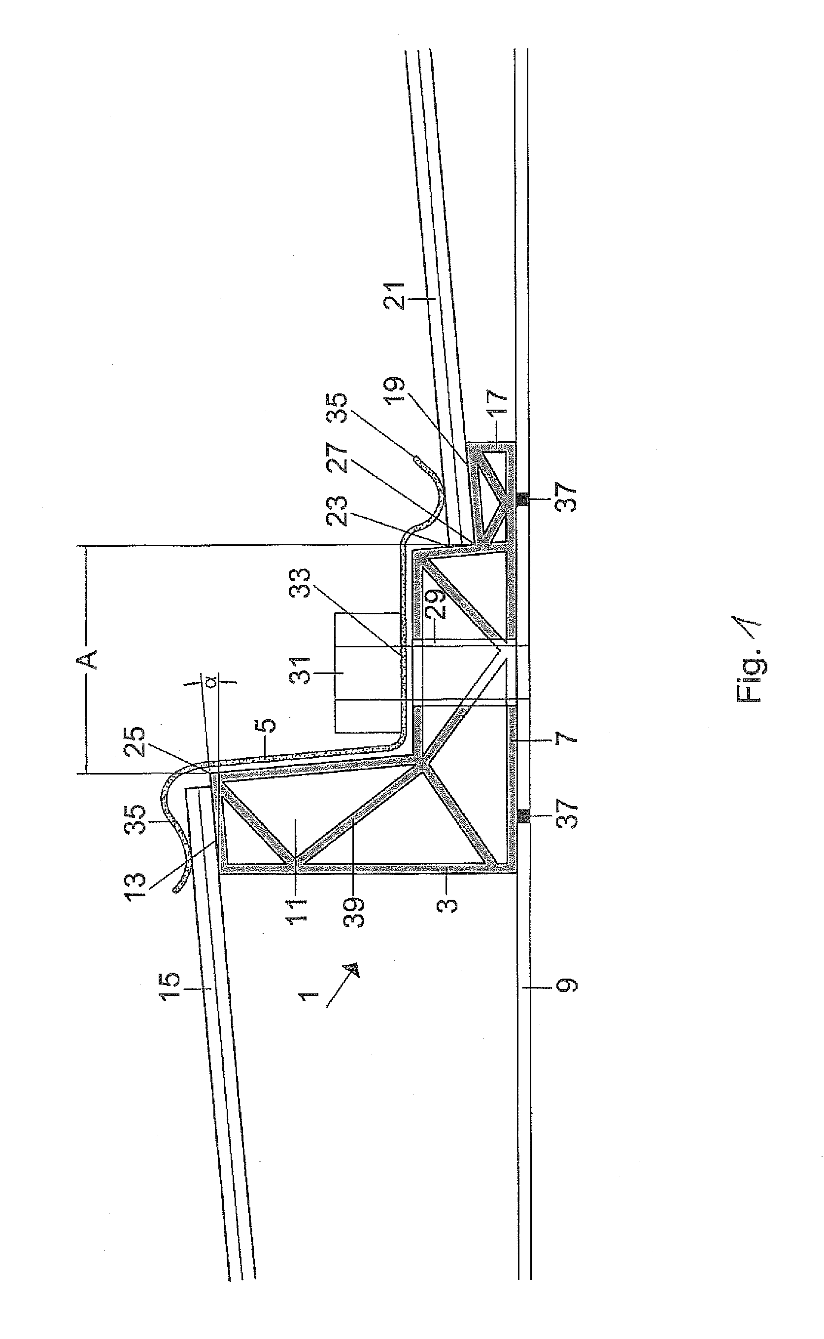
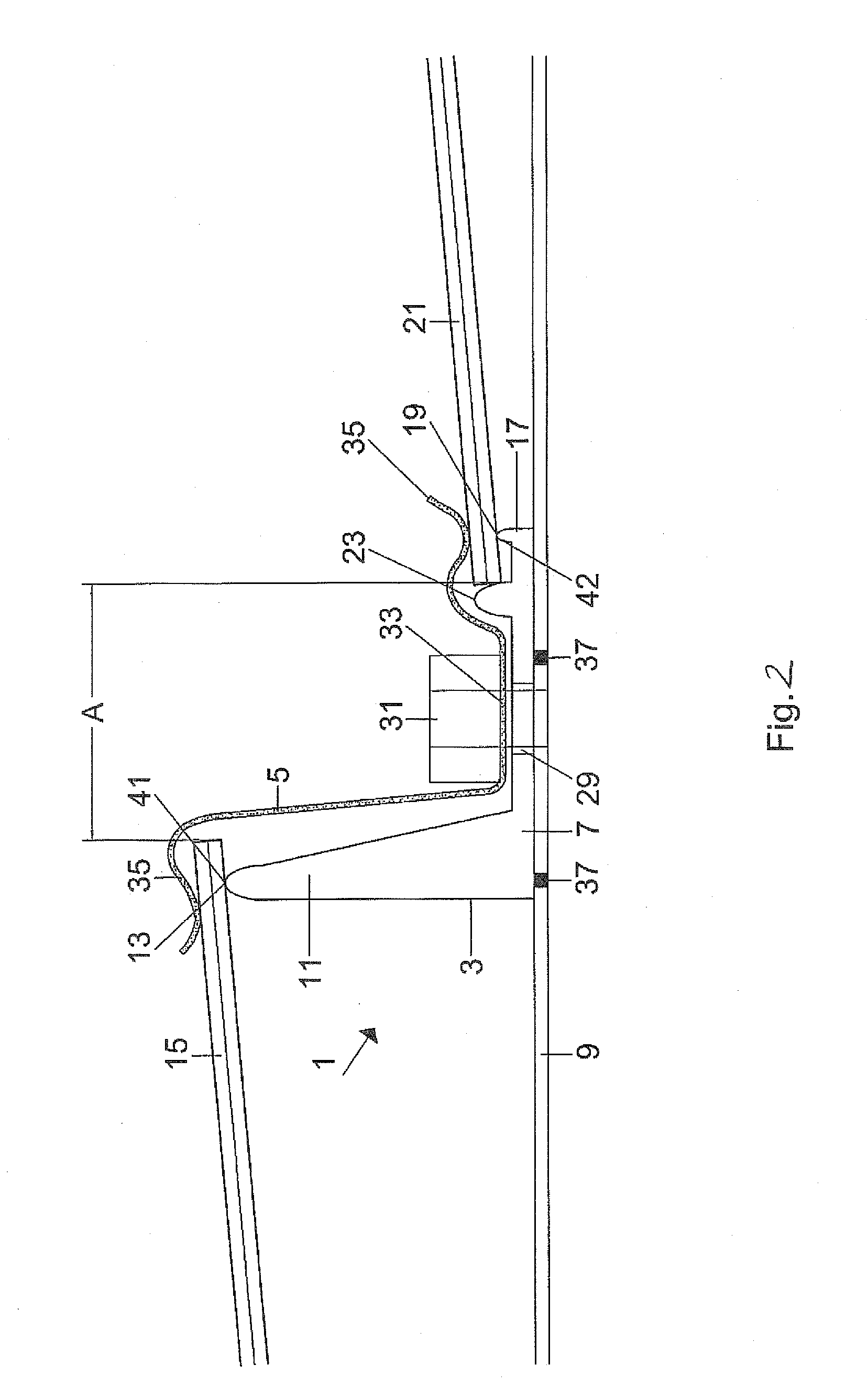
[0022]Turning now to FIG. 1, there is shown a clamp 1 includes a base 3 and a bracket 5. The base 3 has a flat bottom side 7 which is configured to rest flat on a module carrier, for example a module rail 9 or a module band (not shown). A tower-shaped raised portion 11 is located on the right side of the base plate with an upper end that is formed as a two-dimensional surface and ...


PUM

PropertyMeasurementUnit
Heightaaaaaaaaaa
Heightaaaaaaaaaa
Forceaaaaaaaaaa

Abstract

A clamp for attaching rectangular photovoltaic modules on a module rail is constructed so that the upper edge of a first module can be installed at a greater height than the lower edge of a second module. The upper edge of the first module rests on a first supporting surface and the lower edge of the second module rests on a second supporting surface, with the both supporting surfaces disposed on a base and having the same slope. The edges of the modules are affixed on the supporting surfaces by way of a bracket (5). The design of the clamp prevents formation of hollow spaces through which melt water can enter, but from which it cannot drain.

Description

CROSS-REFERENCES TO RELATED APPLICATIONS[0001]This application claims the priority of German Patent Application, Serial No. 10 2009 025 365.3, filed Jun. 18, 2009, pursuant to 35 U.S.C. 119(a)-(d), the content of which is incorporated herein by reference in its entirety as if fully set forth herein.BACKGROUND OF THE INVENTION[0002]The invention relates to a clamp for inclined attachment of rectangular photovoltaic modules on a module rail, wherein the upper edge of a first module can be mounted at a greater height than the lower edge of a second module.[0003]The following discussion of related art is provided to assist the reader in understanding the advantages of the invention, and is not to be construed as an admission that this related art is prior art to this invention.[0004]Clamps of this type are used to attach the photovoltaic modules with a small slope on horizontally extending module rails on flat roofs or roofs with supporting structures, while simultaneously improve the i...

Claims


Application Information

Patent Timeline
IPC IPC(8): F16M13/02B23P17/04
CPCF24J2/5239F24J2/5256Y02B10/12Y10T29/49826Y02E10/50H02S20/00H02S20/23Y02E10/47H02S20/24F24S25/16F24S25/634Y02B10/10
Inventor BECK, BERNHARD
Owner ADENSIS
Why Eureka
Try Eureka