Butler matrix and beam forming antenna comprising same

a beam-forming antenna and butler matrix technology, applied in the field of antennas, can solve the problems of increasing complexity and cost of implementation, affecting the design of antennas, and affecting the appearance of antennas, so as to reduce the size of antennas or more compact, the effect of reducing the size of antennas

Inactive Publication Date: 2010-12-23
SHEN LIN PING
View PDF10 Cites 22 Cited by
  • Summary
  • Abstract
  • Description
  • Claims
  • Application Information

AI Technical Summary

Benefits of technology

[0013]In accordance with another aspect of the invention, there is provided a Butler matrix comprising: a plurality of beam ports and element ports; and a plurality of hybrid elements and phase shifter elements operatively linking said beam ports and said element ports; at least one of said hybrid elements comprising conductive traces on a substantially planar surface, said conductive traces comprising through traces for connecting two inputs and two respective outputs and two or more cross traces connecting said through traces to allow a connection of each of said inputs to each of said outputs; said through traces comprising respective inwardly projecting portions such that said through traces approach one another, thereby decreasing the distance between said inputs and said outputs.
[0015]Since the Butler matrix board disclosed in this invention is reduced or more compact compared to usual Butler matrices due to its multilayer structure, it can help to reduce the size of the antenna for some specific applications. An example of architecture for which this Butler matrix can be useful in reduction of the size, is variable downtilt (VET) architecture. For VET applications, the implementation of Butler matrix as mentioned in this invention can cause size reduction due to the high number of required Butlers.

Problems solved by technology

Some known Butler matrices comprise crossovers on printed circuit boards which involve an additional photomask step, adding complexity and cost to the implementation.
However, they tend to have complicated layouts where the beam ports and element ports are located on all four sides of the circuit layout.
Such complicated layouts may induce other complications when used with beam combiners, such as long transmission lines and / or crossovers required to couple to the beam combiners.
These and other similar designs have various drawbacks, as will be readily apparent to a person of ordinary skill in the art.

Method used


Image

  • Butler matrix and beam forming antenna comprising same
  • Butler matrix and beam forming antenna comprising same
  • Butler matrix and beam forming antenna comprising same

Examples


Embodiment Construction

[0037]Unless defined otherwise, all technical and scientific terms used herein have the same meaning as commonly understood by one of ordinary skill in the art to which this invention belongs.

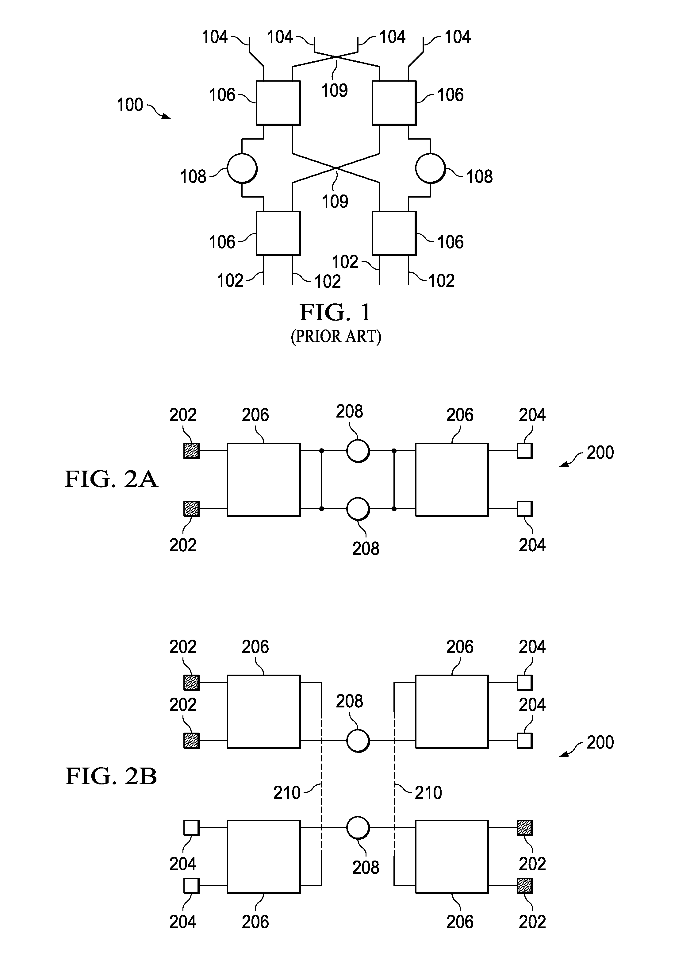
[0038]Referring to FIG. 1 and generally referred to by reference numeral 100, a traditional Butler matrix comprises four beam ports 102, four element ports 104, operatively linked by four hybrid elements 106 and two phase shifters 108. Such a traditional Butler matrix has crossovers 109.

[0039]With reference to FIGS. 2A and 2B and in accordance with one embodiment of the invention, a Butler matrix 200 is shown in schematic form. FIG. 2A shows a footprint of a superimposed two layer Butler matrix, while FIG. 2B shows a footprint of the individual layers separately, with dotted lines 210 indicating linking between the layers. The Butler matrix comprises a plurality of beam ports and element ports. In this embodiment there are four beam ports 202 and four element ports 204. The Butler matrix compri...


PUM


Abstract

The present invention provides a reduced or compact sized Butler matrix with improved performance for use in beam forming antennas and beam forming networks (BFN) applications. The reduced or compact size of the Butler matrix is enabled by shorter transmission lines between the hybrid elements as a result of using multi-layer support surfaces with substantially parallel and overlapping hybrid elements disposed thereon. Moreover, the conductive through traces of the hybrid elements have inwardly projecting and mutually approaching portions, thereby decreasing the distance between the inputs and outputs of the hybrid elements and thus reducing the size of the Butler matrix. Comparing to antennas implemented using traditional Butler matrices, antennas incorporating the present matrix can approximately reduce effective antenna area by half in bi-sector array applications, and are more suitable for complex beam forming antennas such as downtilt antennas or arrays.

Description

CROSS-REFERENCE TO RELATED APPLICATION[0001]This Application relates to and claims priority to U.S. Provisional Patent Application No. 61 / 218,270 filed Jun. 18, 2009, entitled BUTLER MATRIX AND BEAM FORMING ANTENNA COMPRISING SAME, the entirety of which is incorporated herein by reference.FIELD OF THE INVENTION[0002]The invention pertains to the field of antennas and in particular to a Butler matrix and beam forming antenna comprising same.BACKGROUND OF THE INVENTION[0003]Butler matrices are generally used to create a plurality of beams for one or more antenna elements. By arranging the splitting and combining of signals using hybrid elements, a Butler matrix creates multiple beams for antenna elements or an antenna element array. Generally, an N×N Butler matrix will create N beams using N antenna elements. Thus, a 4×4 Butler matrix can be used to generate four orthogonal beams for four antenna elements. Butler matrices are capable of creating multiple beams with minimal losses and ...

Claims


Application Information

Patent Timeline
Patent Type & Authority Applications(United States)
IPC IPC(8): H01Q3/40
CPCH01Q21/061H01Q3/40
Inventor SHEN, LIN-PING
Owner SHEN LIN PING
Why Eureka
Try Eureka