
Pointer detection apparatus and pointer detection method

a detection apparatus and pointer technology, applied in the field of pointer detection apparatus and pointer detection method, can solve the problems of inconvenient practical use of the pointer detection apparatus described above, and the long time required for detection at all cross points

Active Publication Date: 2010-12-23
WACOM CO LTD
View PDF54 Cites 67 Cited by
  • Summary
  • Abstract
  • Description
  • Claims
  • Application Information

AI Technical Summary

Benefits of technology

[0019]In the pointer detection apparatus and the pointer detection method, a plurality of signals produced based on a plurality of code strings having orthogonality and having phases different from each other are supplied at the same time to the plurality of transmission conductors to detect the presence of a pointer on the conductor pattern and the position on the conductor pattern pointed to by the pointer. In other words, a pointer detection process may be carried out simultaneously with respect to a plurality of cross points. Therefore, the present invention makes it possible for a pointer detection apparatus of the cross point electrostatic coupling type to detect the presence of a pointer and the position pointed to by the pointer at a higher speed.
[0020]Furthermore, the present invention makes it possible for a pointer detection apparatus of the electrostatic coupling system to carry out position detection of multiple positions (i.e., multiple positions of multiple pointers, or of multiple fingers of one or more users) at the same time.

Problems solved by technology

Since such a conventional pointer detection apparatus of the cross point electrostatic coupling system as described above carries out a position detection process of a pointer for each cross point, it has a problem in that a long period of time is required for detection at all cross points.
Therefore, the pointer detection apparatus as described above is not quite suitable for practical use.

Method used


Image

  • Pointer detection apparatus and pointer detection method
  • Pointer detection apparatus and pointer detection method
  • Pointer detection apparatus and pointer detection method

Examples


first embodiment

1. First Embodiment

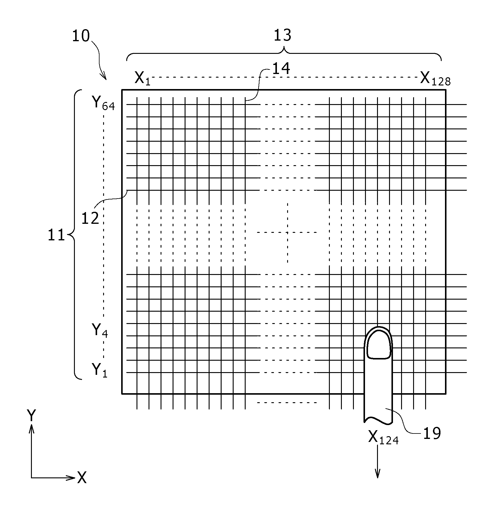
[0103]In a first embodiment of the present invention, a basic configuration of an exemplary pointer detection apparatus and a pointer detection method of the present invention are described. An electrostatic coupling method for detecting the position of a pointer based on the variation of an electrostatic coupling state between a transmission conductor and a reception conductor of a sensor section is used in the present embodiment. Further, in the present embodiment, an example of a configuration is described wherein spread codes, each in the form of a code string, are supplied at the same time to all transmission conductors such that signal detection is carried out at the same time through reception conductors.

[Configuration of the Pointer Detection Apparatus]

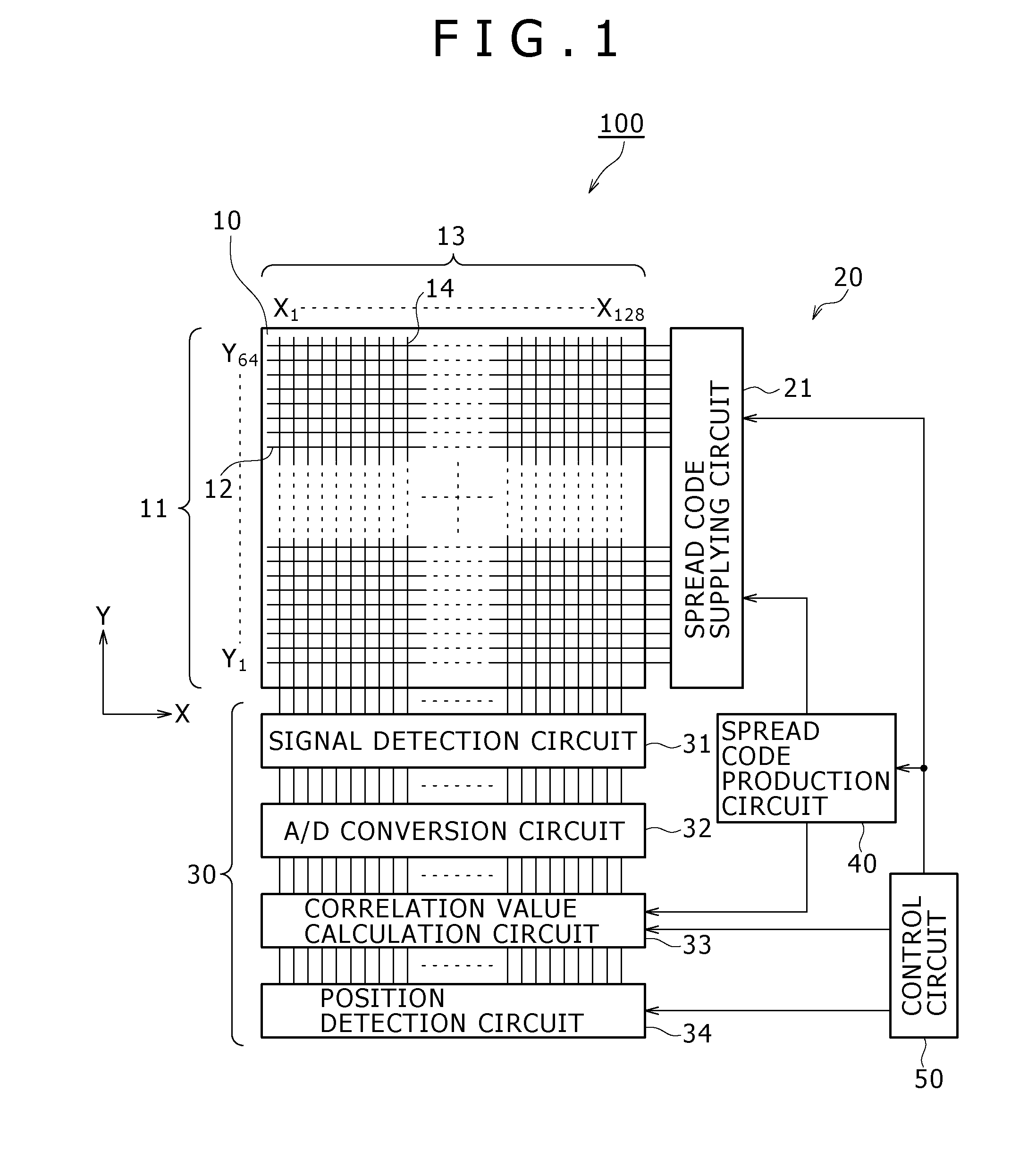
[0104]FIG. 1 shows a general configuration of the pointer detection apparatus according to the first embodiment. A pointer detection apparatus 100 includes a sensor section 10, which is a conductor pattern, ...

modification 1

[Modification 1]

[0188]While the first embodiment described above illustrates an example where spread codes to be supplied to each correlator 33f and the transmission conductors 12 are produced using the spread code production circuit 40 and the shift registers in the spread code supplying circuit 21, the present invention is not limited to this particular implementation. The production of spread codes can be implemented also by providing the transmission section with a storage circuit formed from a ROM, or a random logic section wherein a predetermined logic function is formed by combining logic circuits such as an AND circuit, an OR circuit, an inverter, a flip-flop, or a like circuit, such that data to be supplied to the transmission conductors 12 is stored in and read out from the storage circuit. Further, the spread codes having the phase differences from each other may be stored in advance so that, upon position detection, signals based on the spread codes are supplied from the...

second embodiment

2. Second Embodiment

[0194]While in the first embodiment described above spread codes are supplied directly to the transmission conductor array 11, the present invention is not limited to this implementation. A signal obtained by applying predetermined modulation to spread codes may be supplied to the transmission conductor array 11. In a second embodiment described below, the pointer detection circuit is configured such that spread codes to be supplied to the transmission conductor array 11 are PSK (Phase Shift Keying) modulated.

[PSK Modulation]

[0195]FIGS. 20A and 20B illustrate waveforms of spread codes before and after PSK modulation. In particular, FIG. 20A illustrates a waveform of spread codes before PSK modulation and FIG. 20B illustrates a waveform of the spread codes after the PSK modulation.

[0196]In the embodiment described below, spread codes are PSK modulated with a signal of a clock frequency that is twice the clock frequency of the spread codes before the modulation (i....


PUM


Abstract

A pointer detection apparatus includes a conductor pattern with first conductors disposed in a first direction and second conductors disposed in a second direction that crosses the first direction, and a code string signal production circuit for producing signals based on orthogonal code strings with phases different from each other and supplying the produced signals to the first conductors. The apparatus also includes a signal detection circuit connected to the second conductors for detecting a signal corresponding to a variation of electrostatic capacitance between the conductor pattern and a pointer, an analog to digital conversion (ADC) circuit for converting the signal output from the signal detection circuit into a digital signal comprising a word string of multiple bits, and a correlation detection circuit for determining correlation values between the code strings and the word string. The apparatus also includes a memory for storing correlation values successively output from the correlation detection circuit, wherein the pointer is detected based on the correlation values.

Description

CROSS REFERENCES TO RELATED APPLICATIONS[0001]The present application claims priority under 35 U.S.C. §119 from Japanese Patent Application JP 2009-145880 filed in the Japanese Patent Office on Jun. 18, 2009, the entire content of which is incorporated herein by reference.BACKGROUND OF THE INVENTION[0002]1. Field of the Invention[0003]This invention relates to a pointer detection apparatus and a pointer detection method, and more particularly to a pointer detection apparatus and a pointer detection method wherein a pointer is detected by an electrostatic coupling system.[0004]2. Description of the Related Art[0005]Conventionally, for the detection of a position of a pointer used with a touch panel or a like apparatus, various sensor systems have been proposed such as a resistive film system and an electrostatic coupling system (electrostatic capacitive system). In recent years, a pointer detection apparatus incorporating an electrostatic coupling system has been vigorously developed...

Claims


Application Information

Patent Timeline
IPC IPC(8): G06F3/045G06F3/044
CPCG06F3/044G06F3/0416G06F3/04166G06F3/0445G06F3/0446G06F2203/04111
Inventor ODA, YASUOSUGIYAMA, YOSHIHISAYAMAMOTO, SADAO
Owner WACOM CO LTD
Features
  • Generate Ideas
  • Intellectual Property
  • Life Sciences
  • Materials
  • Tech Scout
  • Unparalleled Data Quality
  • Higher Quality Content
  • 60% Fewer Hallucinations
Learn More