

Cable for Display and Television System
- Summary
- Abstract
- Description
- Claims
- Application Information
AI Technical Summary
Benefits of technology
Problems solved by technology
Method used
Image

Examples
first embodiment
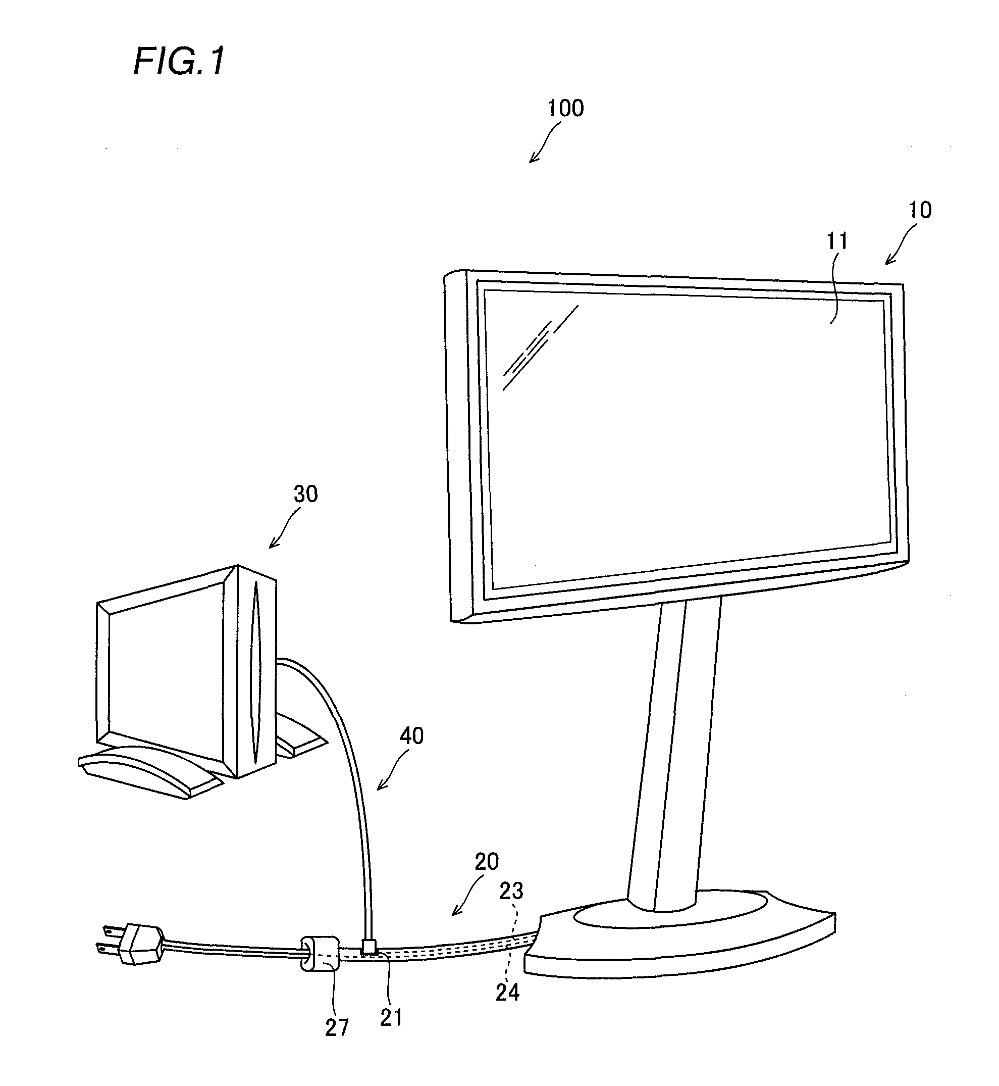
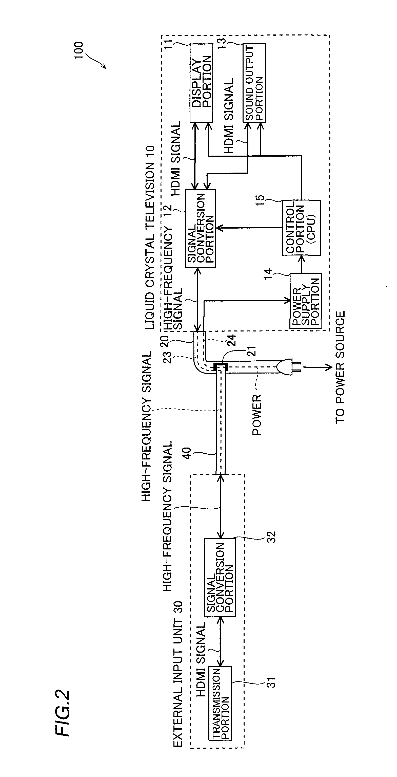
[0046]The structure of a television system 100 according to a first embodiment of the present invention is described with reference to FIGS. 1 to 4.
[0047]The television system 100 according to the first embodiment of the present invention is mainly constituted of a liquid crystal television 10 including a display portion 11 displaying an image corresponding to an image signal, a liquid crystal television cable 20 mounted on the liquid crystal television 10, an external input unit 30 consisting of a BD (Blu-ray Disc) player or a tuner unit for transmitting the image signal for displaying the image on the display portion 11 and a LAN (Local Area Network) cable 40 mounted on the external input unit 30, as shown in FIG. 1. The LAN cable 40 is an example of the “second LAN cable” in the present invention. The liquid crystal television 10 is an example of the “display” or the “television set” in the present invention, and the liquid crystal television cable 20 is an example of the “cable ...
second embodiment
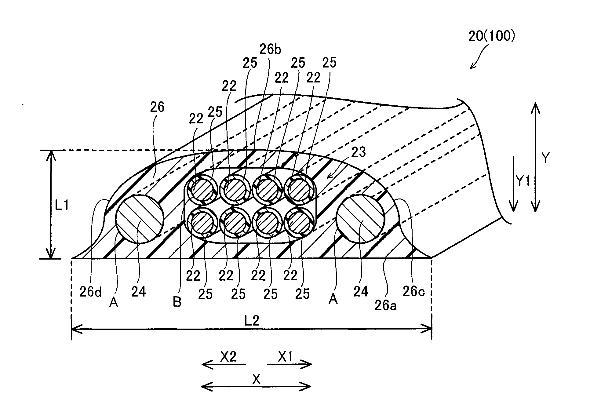
[0071]The structure of a television system 101 according to a second embodiment of the present invention is now described with reference to FIG. 5. In the television system 101 according to the second embodiment, a second protective coating 126 of a liquid crystal television cable 120 has a rectangular outer shape, dissimilarly to the first embodiment in which the second protective coating 26 of the liquid crystal television cable 20 has the substantially trapezoidal outer shape (shape close to a trapezoidal shape). The liquid crystal television cable 120 is an example of the “cable for a display” or the “cable for a television set” in the present invention.
[0072]The second protective coating 126 of the liquid crystal television cable 120 according to the second embodiment is formed to have a substantially rectangular (flat) outer shape. More specifically, the second protective coating 126 of the liquid crystal television cable 120 has such a horizontally elongated rectangular shape...
third embodiment
[0076]The structure of a television system 102 according to a third embodiment of the present invention is now described with reference to FIG. 6. In the television system 102 according to the third embodiment, a second protective coating 226 of a liquid crystal television cable 220 has a horizontally elongated elliptical outer shape, dissimilarly to the first embodiment in which the second protective coating 26 of the liquid crystal television cable 20 has the substantially trapezoidal outer shape (shape close to a trapezoidal shape). The liquid crystal television cable 220 is an example of the “cable for a display” or the “cable for a television set” in the present invention.
[0077]The second protective coating 226 of the liquid crystal television cable 220 according to the third embodiment is formed to have the elliptical (flat) outer shape. More specifically, the second protective coating 226 of the liquid crystal television cable 220 is so formed that the length (cable thickness...
PUM
 Abstract
Description
Claims
Application Information