Vehicle, system including the same, vehicle motion producing method

a technology of vehicle motion and system, applied in vehicle position/course/altitude control, process and machine control, instruments, etc., can solve the problems of user anxiety about the vehicle,

Inactive Publication Date: 2010-12-23
TOYOTA JIDOSHA KK
View PDF18 Cites 67 Cited by
  • Summary
  • Abstract
  • Description
  • Claims
  • Application Information

AI Technical Summary

Benefits of technology

[0010]A first exemplary aspect of the present invention is a vehicle that executes motion by modifying motion based on a motion direction of a user on board accordin

Problems solved by technology

For example, there is a case where the user feels anxiety about the vehicle because the vehicle starts moving with a higher speed than expected.
There is also a case where the user feels anxiety about the vehicle because the vehicle corner

Method used


Image

  • Vehicle, system including the same, vehicle motion producing method
  • Vehicle, system including the same, vehicle motion producing method
  • Vehicle, system including the same, vehicle motion producing method

Examples


first exemplary embodiment

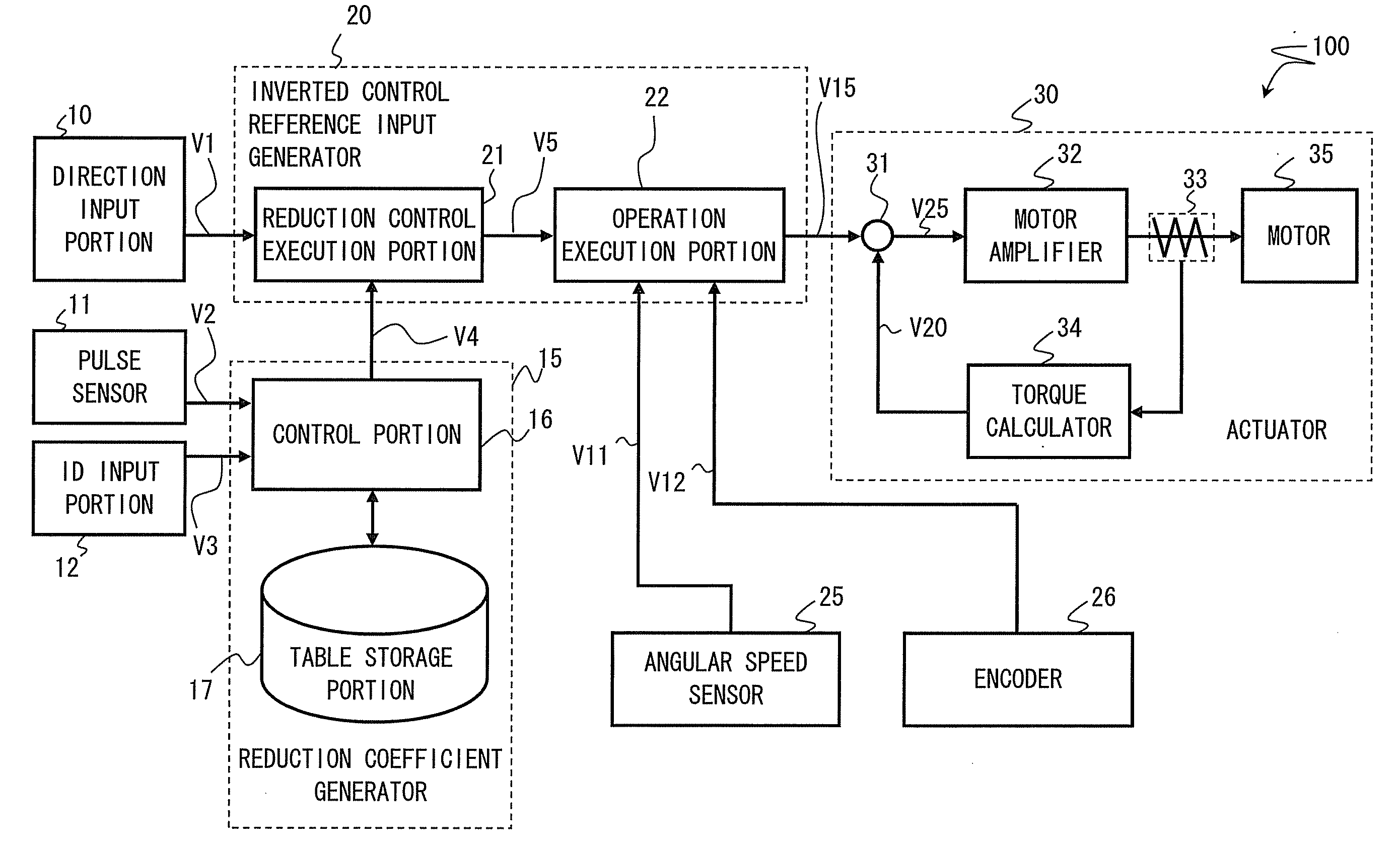
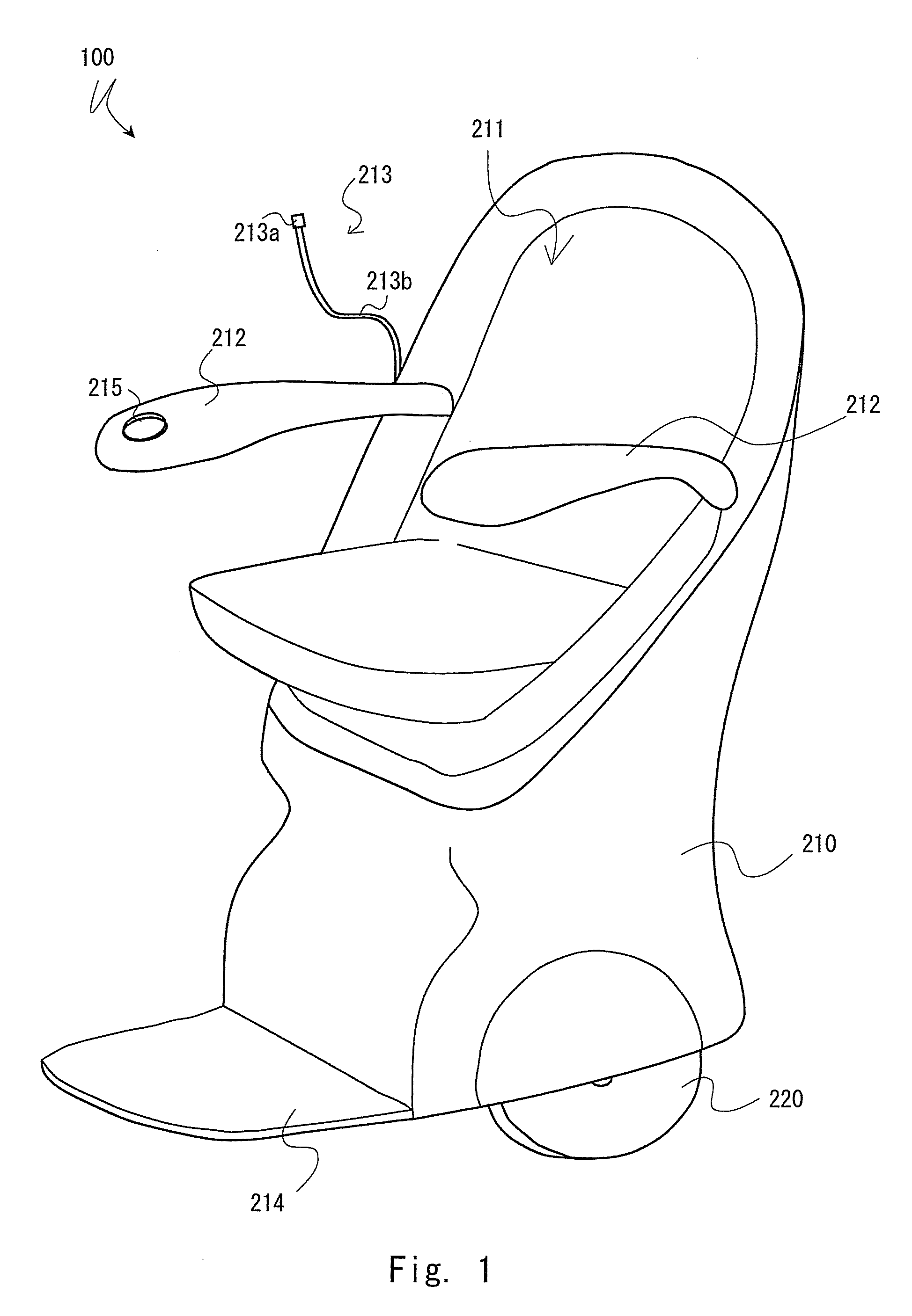
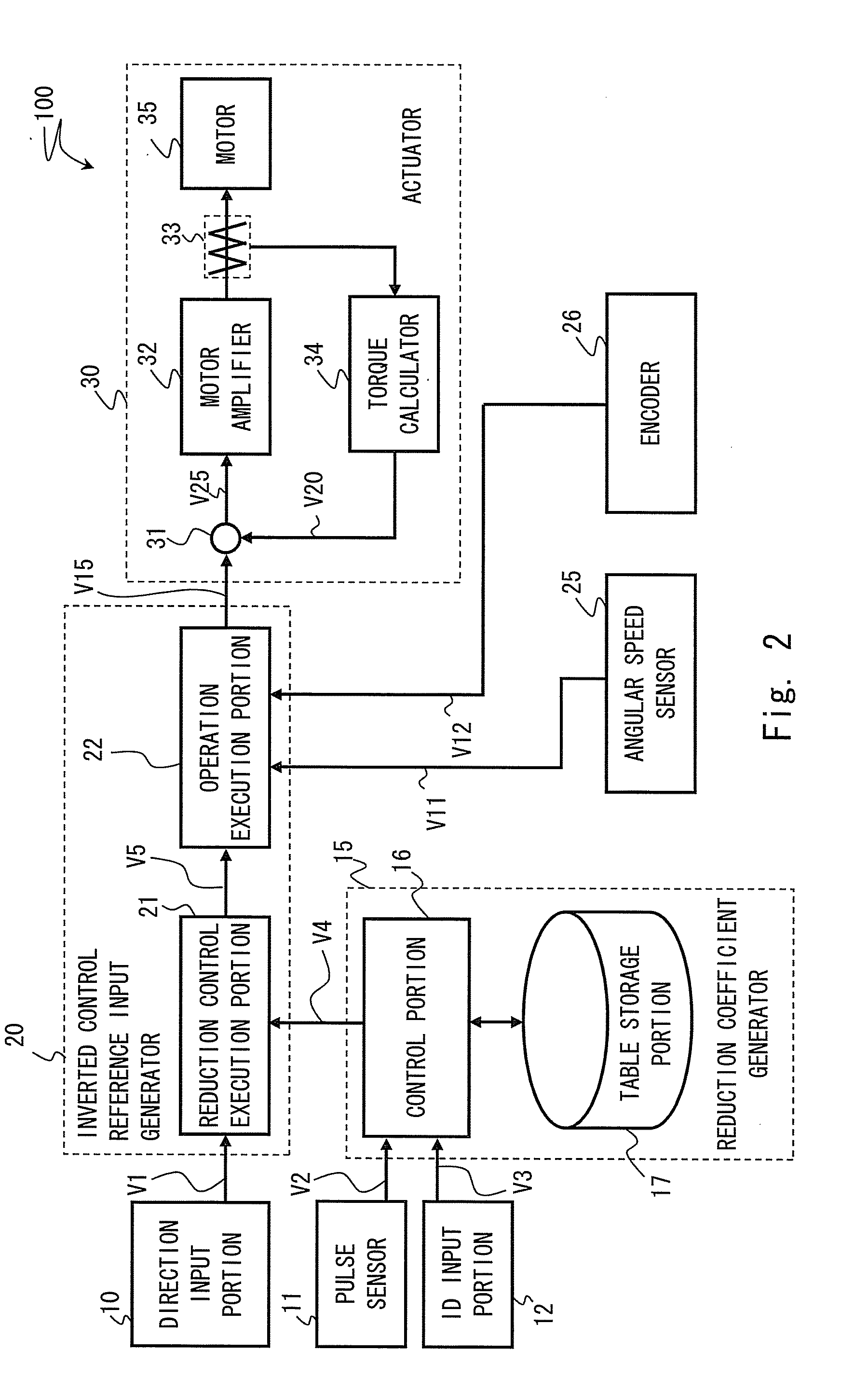
[0047]A first exemplary embodiment of the present invention is described hereinafter with reference to FIGS. 1 to 8. FIG. 1 is a schematic perspective view of an inverted two-wheeled robot. FIG. 2 is a schematic block diagram of the inverted two-wheeled robot. FIG. 3 is an explanatory view showing an overview of anxiety reduction control. FIG. 4 is an explanatory view showing a structure of a table. FIG. 5 is an explanatory view showing an overview of anxiety reduction control. FIGS. 6 to 8 are schematic flowcharts showing the motion of the inverted two-wheeled robot.

[0048]Referring to FIG. 1, an inverted two-wheeled robot 100 includes a body 210 and a wheel 220. The body 210 includes a seat 211, a pair of armrests 212, a sensor unit 213, and a footrest 214. A ball controller 215 is placed at the end of the armrest 212. The sensor unit 213 is made up of a sensor part 213a and a wire part 213b. The body 210 has various kinds of built-in electrical / mechanical components such as variou...

second exemplary embodiment

[0100]A second exemplary embodiment of the present invention is described hereinafter with reference to FIGS. 9 and 10. FIG. 9 is a schematic block diagram of an inverted two-wheeled robot. FIG. 10 is a schematic block diagram of a transmit / receive portion in the inverted two-wheeled robot.

[0101]Referring to FIG. 9, a system 1000 includes a plurality of robots 100 and an information processing server 200. In this exemplary embodiment, the reduction coefficient generator 15, which has been placed in the robot 100 in the first exemplary embodiment, is integrated into the information processing server 200. It is thereby possible to share the reduction coefficient for each user that is held in each robot 100.

[0102]As shown in FIG. 9, the robot 100 includes a robot ID holding portion 13 and an information communication portion 40. The information communication portion 40 includes a control portion 41 and a transmit / receive portion 42. The information processing server 200 includes a tran...

third exemplary embodiment

[0110]A third exemplary embodiment of the present invention is described hereinafter with reference to FIGS. 11 and 12. FIG. 11 is a schematic block diagram of an inverted two-wheeled robot. FIG. 12 is a schematic perspective view of the inverted two-wheeled robot.

[0111]In this exemplary embodiment, differently from the first exemplary embodiment, the amount of sweating of a user is measured instead of the pulse of a user. In such a case also, the same advantage as that of the first exemplary embodiment can be obtained. A specific technique of anxiety reduction control is the same as described in the first exemplary embodiment.

[0112]Referring to FIG. 11, the robot 100 includes a sweat sensor (sensor) 91. An output terminal of the sweat sensor 91 is connected to the control portion 16. The sweat sensor 91 measures the amount of sweating by an arbitrary means. For example, the amount of sweating may be measured by using a humidity sensor. Alternatively, a ventilating capsule sweat met...


PUM


Abstract

A robot executes motion by modifying a motion behavior on the basis of a motion direction of a user on board according to a state of mind of the user on board. This produces the motion of the vehicle under conditions that reflect the user's state of mind. The robot preferably includes a direction input portion that receives the motion direction from the user and generates a reference input corresponding to the motion direction, and an inverted control reference input generator that generates a motion reference input that makes the robot execute motion in a behavior different from the motion behavior on the basis of the motion direction, based at least on a reduction coefficient with a value corresponding to the user's state of mind and the reference input generated in the direction input portion. The reduction coefficient is determined by measuring the pulse rate of the user on board.

Description

INCORPORATION BY REFERENCE[0001]This application is based upon and claims the benefit of priority from Japanese patent application No. 2009-144083, filed on Jun. 17, 2009, the disclosure of which is incorporated herein in its entirety by reference.BACKGROUND OF THE INVENTION[0002]1. Field of the Invention[0003]The present invention relates to a vehicle, a system including the same, a vehicle motion producing method, and a program storage medium.[0004]2. Description of Related Art[0005]Recently, technology related to robots used for the spatial movement of humans has become significantly advanced with development of robot technology. For a moving robot, stability and safety during movement are strongly demanded. In order to ensure the stability and safety during movement of a robot, it is strongly demanded to execute posture control of a robot with high accuracy based on inputs of various sensors. A body of a robot that functions as a vehicle has various kinds of built-in electrical / ...

Claims


Application Information

Patent Timeline
IPC IPC(8): G06F19/00B60L15/20B62K3/00B62K17/00
CPCY02T10/7258B62K3/007B62K11/007Y02T10/72
Inventor OKUMATSU, YOSHIHIRO
Owner TOYOTA JIDOSHA KK
Why Eureka
Try Eureka