
Determination of complex dielectric constants from electromagnetic propagation measurements

a dielectric constant and complex technology, applied in the field of interpretation of electromagnetic measurements, can solve the problem of time-consuming computation steps in iteration

Inactive Publication Date: 2010-12-23
SCHLUMBERGER TECH CORP
View PDF5 Cites 8 Cited by
  • Summary
  • Abstract
  • Description
  • Claims
  • Application Information

AI Technical Summary

Problems solved by technology

These computations are the most time-consuming step in the iteration.

Method used


Image

  • Determination of complex dielectric constants from electromagnetic propagation measurements
  • Determination of complex dielectric constants from electromagnetic propagation measurements
  • Determination of complex dielectric constants from electromagnetic propagation measurements

Examples


Embodiment Construction

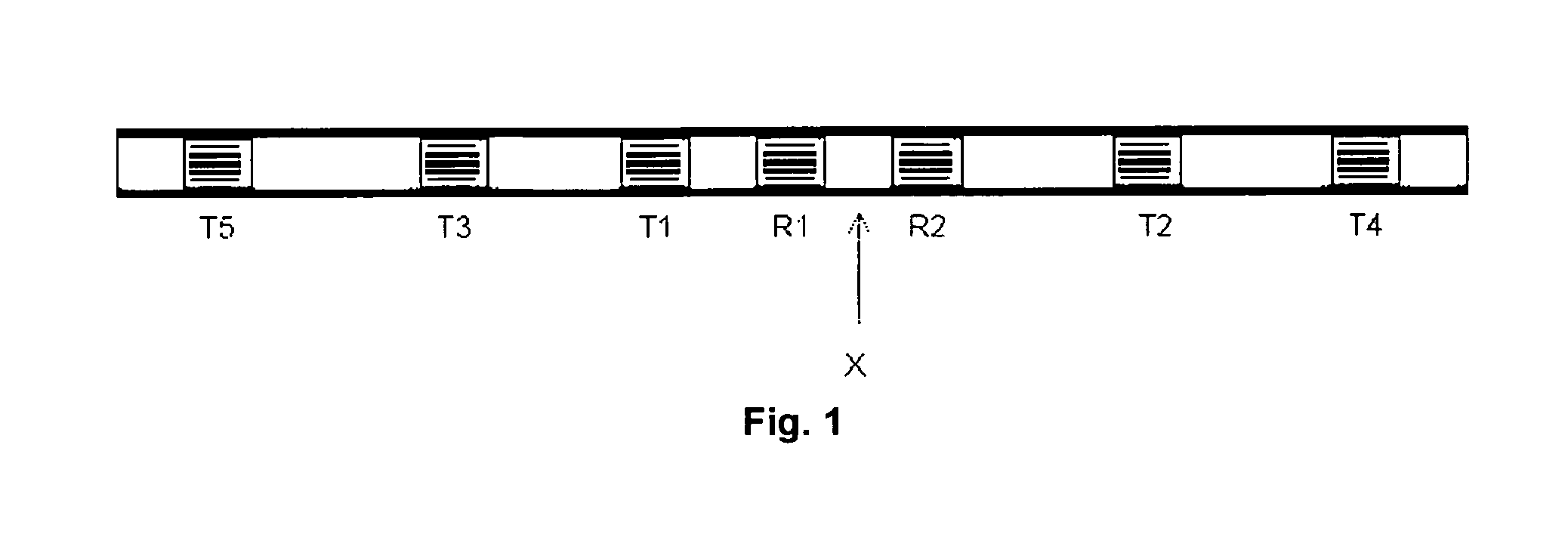
[0021]Any electromagnetic-propagation measurement emits a signal from a transmitter and detects it at a receiver. The received signal differs in amplitude and phase from the emitted signal. In general it is written as complex-valued receiver voltage U* with its amplitude A and phase φ:

U*=Aeiφ=U0eα+iφ

[0022]Here a voltage U0 of arbitrary normalization describes the transmitter signal, so that the transmitter amplitude and an exponential replace the receiver amplitude

A=U0eα.

[0023]Commonly, the received signal is given as the logarithm of this voltage, where the transmitter amplitude is discarded; the phase is converted to degrees and the amplitude to decibel (dB):

-ln(U*)=-ln(U0)+φ-a->180∘πφ-20ln(10)a

[0024]The factors 180° / π and 20 / ln(10) convert radian to degree and natural logarithm to decibel, respectively. They are merely engineering conventions without any scientific significance and are not used further here.

[0025]For an electromagnetic propagation tool with a differential receive...


PUM


Abstract

A method of determining the dielectric constant of a formation, comprising acquiring phase-related and amplitude-related measurements for electromagnetic signals propagating though the formation from a transmitter to a receiver; deriving a complex-valued quantity comprising terms relating to the phase shift and attenuation of the signals; defining a one-component complex-valued relationship relating the phase shift, attenuation and complex dielectric constant; and using the derived complex-valued quantity in the defined relationship to obtain a calculated value of the complex dielectric constant. An apparatus for determining the dielectric constant of a formation, comprises a transmitter for transmitting electromagnetic signals into the formation; a receiver for receiving the electromagnetic signals that have propagated from the transmitter through the formation; and means for determining the dielectric constant of the formation in accordance with a method according to the first aspect of the invention.

Description

TECHNICAL FIELD[0001]This invention relates to the interpretation of electromagnetic measurements in underground formations. In particular, the invention relates to the determination of dielectric constants from electromagnetic propagation measurements. Such measurements can be made in oil and gas wells and are useful for the evaluation of the formations through which the well passes.BACKGROUND ART[0002]Electromagnetic waves have long been used to measure the saturation and salinity of water in porous rocks. The electromagnetic measurements use propagating radio waves and determine the phase and amplitude of the received signal for known transmitter-receiver geometries and operating frequencies. These phase and amplitude measurements are independent; they are converted to apparent dielectric permittivity and electric conductivity for some tools, such as the Electromagnetic Propagation Tool (EPT) or the Deep Propagation Tool (DPT), both of Schlumberger.[0003]Electromagnetic-propagati...

Claims


Application Information

Patent Timeline
Patent Type & Authority Applications(United States)
IPC IPC(8): G01V3/38
CPCG01V3/30
Inventor LULING, MARTIN G.
Owner SCHLUMBERGER TECH CORP
Learn More