Cooling chamber assembly for a gasifier

a gasifier and cooling chamber technology, applied in the field of gasifiers, can solve the problems of excessive liquid carried from the cooling chamber and into downstream equipment, and operational problems

Inactive Publication Date: 2010-12-30
GENERAL ELECTRIC CO
View PDF16 Cites 19 Cited by
  • Summary
  • Abstract
  • Description
  • Claims
  • Application Information

AI Technical Summary

Benefits of technology

[0005]There is a need for an improved cooling chamber assembly for both quench and scrubber applications configured to remove entrained liquid content substantially from an effluent gas generated in a gasifier.

Problems solved by technology

However, excessive liquid carried from the cooling chamber and into downstream equipment, is found to pose operational problems.

Method used


Image

  • Cooling chamber assembly for a gasifier
  • Cooling chamber assembly for a gasifier
  • Cooling chamber assembly for a gasifier

Examples


Embodiment Construction

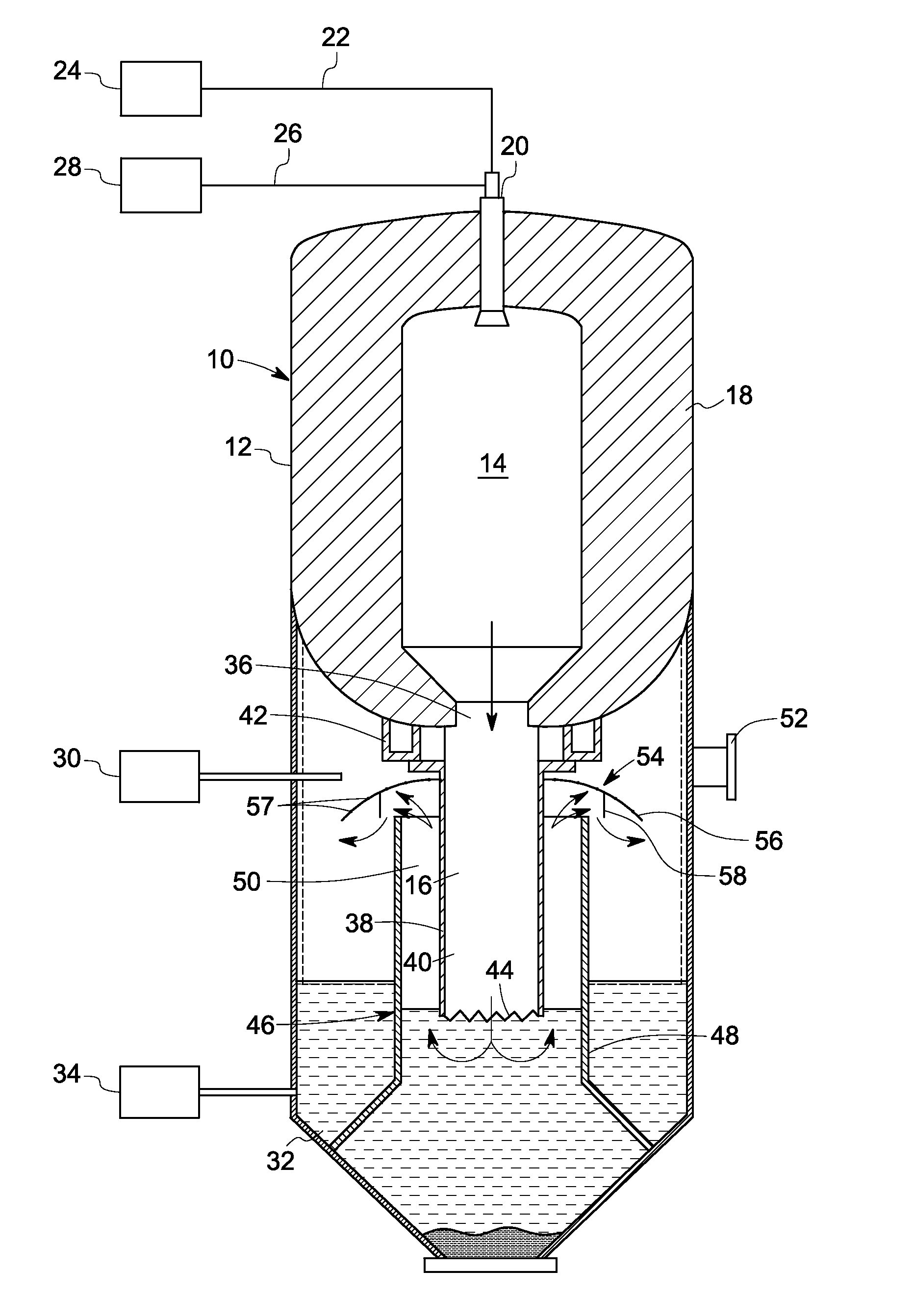
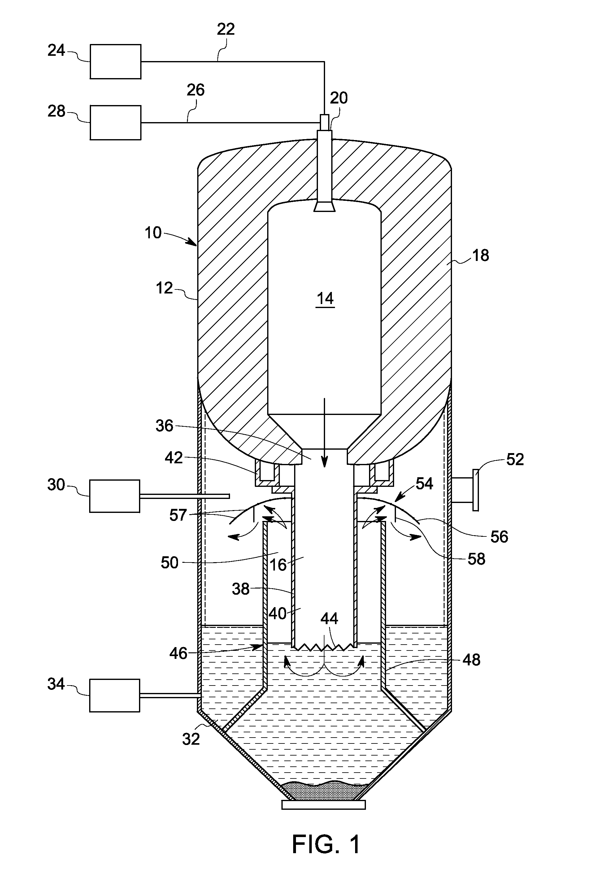
[0027]In accordance with the exemplary embodiments disclosed herein, a gasifier having a cooling chamber assembly configured to reduce temperature of syngas downstream of a combustion chamber is disclosed. The gasifier includes a cooling chamber containing a liquid coolant disposed downstream of the combustion chamber. A syngas generated from the combustion chamber is directed via a dip tube to the cooling chamber to contact the liquid coolant and produce a cooled syngas. The gasifier also includes a dip tube coupling the combustion chamber to the cooling chamber and configured to direct syngas from the combustion chamber to the cooling chamber to contact the liquid coolant and produce a cooled syngas. A draft tube is disposed surrounding the dip tube and defining an annular passage there between. A liquid separator is disposed proximate to an exit path of the cooling chamber and configured to remove entrained liquid content from the cooled syngas directed through the annular passag...


PUM

PropertyMeasurementUnit
temperaturesaaaaaaaaaa
pressuresaaaaaaaaaa
temperatureaaaaaaaaaa

Abstract

A gasifier includes a combustion chamber in which a combustible fuel is burned to produce a syngas and a particulated solid residue. A cooling chamber having a liquid coolant is disposed downstream of the combustion chamber. A dip tube is disposed coupling the combustion chamber to the cooling chamber. The syngas is directed from the combustion chamber to the cooling chamber via the dip tube to contact the liquid coolant and produce a cooled syngas. An asymmetric or symmetric liquid separator is disposed proximate to an exit path of the cooling chamber and configured to remove entrained liquid content from the cooled syngas directed through the annular passage to the exit path.

Description

CROSS-REFERENCE TO RELATED PATENT APPLICATIONS[0001]This application is related to the following co-pending United States patent applications having Serial No. {Attorney Docket No. 235585-1}, entitled “QUENCH CHAMBER ASSEMBLY FOR A GASIFIER” and Serial No. {Attorney Docket No. 236150-1}, entitled “GASIFICATION SYSTEM FLOW DAMPING” assigned to the same assignee as this application and filed concurrently herewith, each of which is hereby incorporated by reference.BACKGROUND[0002]The invention relates generally to gasifiers, and more particularly to a cooling chamber assembly for a gasifier.[0003]In a normal coal gasification process, wherein a particulated carbonaceous fuel such as coal or coke or a carbonaceous gas is burned, the process is carried out at relatively hot temperatures and high pressures in a combustion chamber. When injected fuel is burned or partially burned in the combustion chamber, an effluent is discharged through a port at a lower end of the combustion chamber to...

Claims


Application Information

Patent Timeline
Patent Type & Authority Applications(United States)
IPC IPC(8): C10J3/20
CPCC10J3/485C10J3/84C10J3/845C10J3/526C10J2300/0959C10J3/76C10J2300/093C10J2300/0943C10J2300/0956C10J3/74B01D51/00C10J3/46F02C6/00F02C7/18F23D99/00F23J15/06F28C3/06
Inventor DINU, CONSTANTINCORRY, JUDETH BRANNONSTOREY, JAMES MICHAELRICO, DENISE MARIEZHAO, RICHARD L.
Owner GENERAL ELECTRIC CO
Why Eureka
Try Eureka