Welding inspection method and welding inspection apparatus

a welding inspection and welding technology, applied in the direction of analysing solids using sonic/ultrasonic/infrasonic waves, measuring devices, instruments, etc., can solve the problems of affecting inspection work efficiency, easy wear and/or damage of contact parts, and hardly being able to eliminate uncertainty, so as to improve inspection work efficiency and avoid wear and/or damage. easy

Inactive Publication Date: 2010-12-30
HINO MOTORS LTD
View PDF10 Cites 2 Cited by
  • Summary
  • Abstract
  • Description
  • Claims
  • Application Information

AI Technical Summary

Benefits of technology

[0038]According to the present invention, the welding inspection can be carried out accurately, being irrelevant to the skill level of the inspector. Furthermore, the probe is not wo...

Problems solved by technology

If an inspector carries out the placement and alignment manually, it is hardly possible to eliminate uncertainty about the inspection accuracy depending on a skill level of the inspector.
However, whe...

Method used


Image

  • Welding inspection method and welding inspection apparatus
  • Welding inspection method and welding inspection apparatus
  • Welding inspection method and welding inspection apparatus

Examples


Embodiment Construction

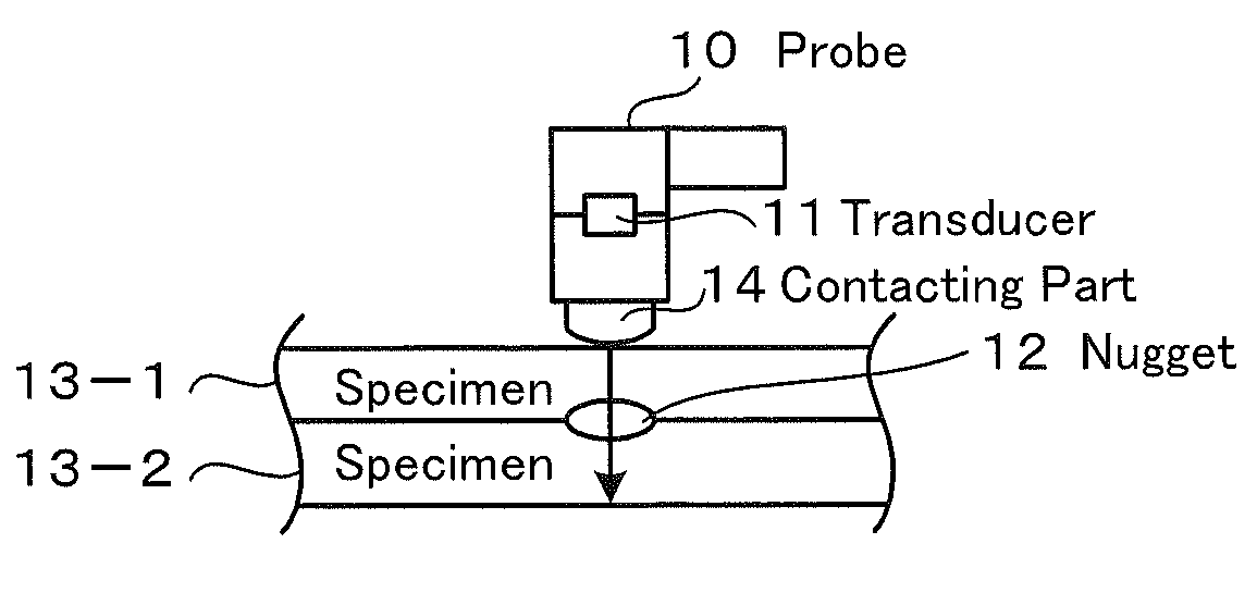
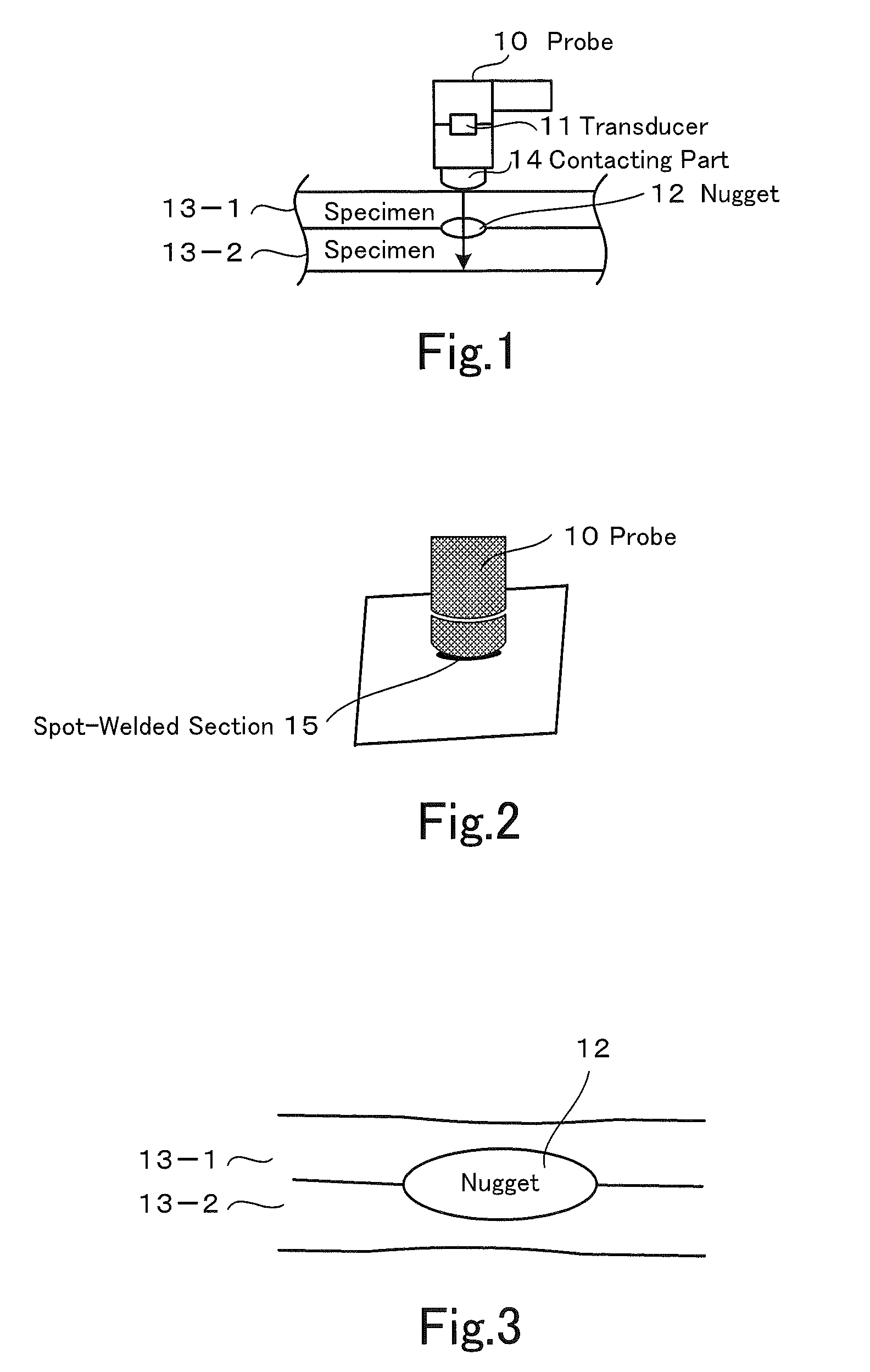
[0067]An embodiment of the present invention is described below with reference to FIG. 10 through FIG. 23. FIG. 10 is a block diagram of a welding inspection apparatus according to an embodiment of the present invention. As shown in FIG. 10, the welding inspection apparatus according to the embodiment of the present invention includes a probe 1 to be temporarily placed in the proximity of a welded section on a surface of a steel plate 13-1, and a transducer 2 as means for launching an ultrasonic wave to a boundary plane between steel plates 13-1 and 13-2 from an oblique direction through the probe 1.

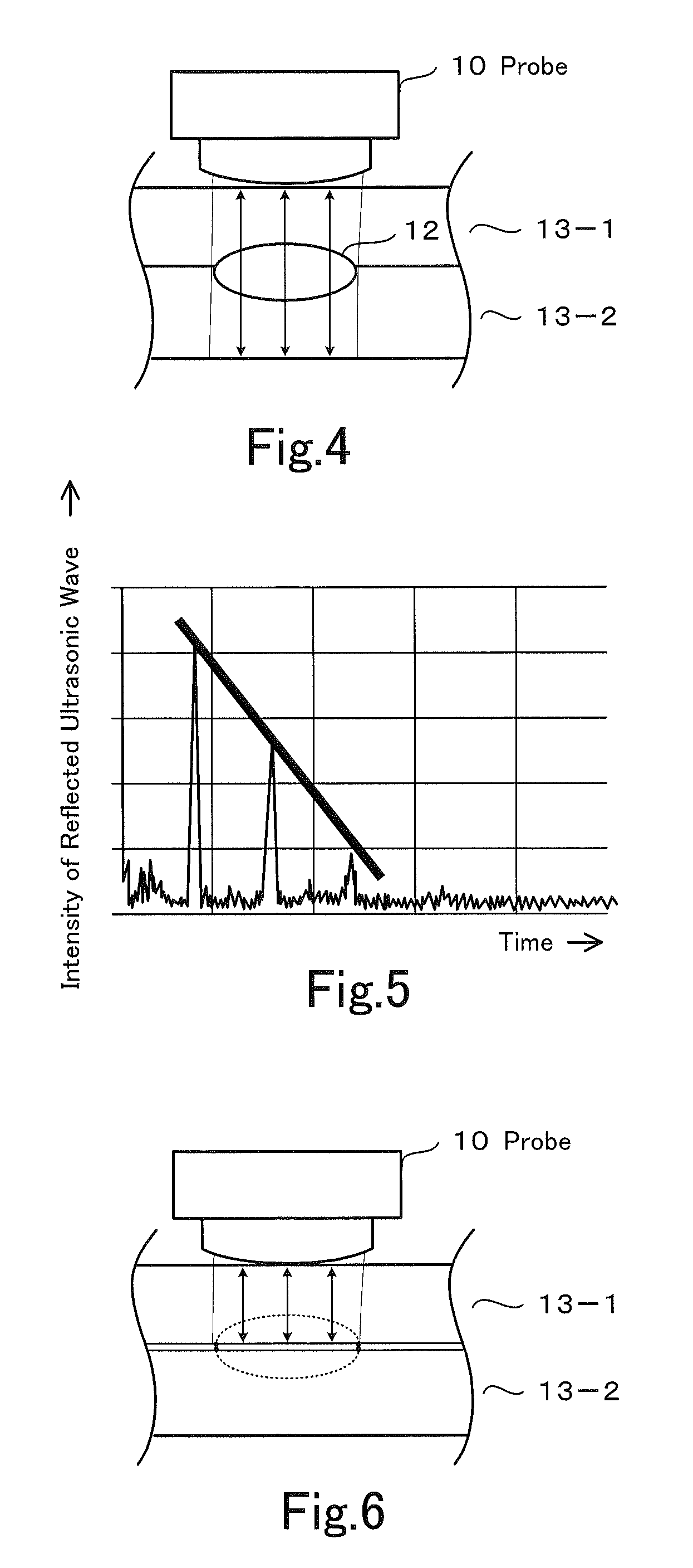
[0068]Furthermore, the welding inspection apparatus includes a display processing part 8 as display processing means for displaying an image of a reflected wave of the ultrasonic wave. In another configuration, the display processing part 8 may be display processing means for displaying the contents of an inspection result estimated according to an intensity of the reflected wave of the ...


PUM


Abstract

Disclosed is a welding inspection method which does not require the inspector to be highly skilled, does not require waiting for the spot welded part to cool off, and with which the probe is not consumed or damaged. A probe temporarily mounted close to the welded part on the surface of a metal plate emits ultrasonic waves from an oblique direction with respect to the boundary surfaces between a plurality of metal plates. At this time, the probe is temporarily mounted at the position where the incident ultrasonic waves pass through the welded part at the boundary between the plurality of metal plates in an oblique direction with respect to the boundary surface. Also, a display processing means displays the intensity of the refrected ultrasonic waves. Alternatively, the display processing means displays the details of the detection result estimated based on the intensity of the reflected ultrasonic waves.

Description

CROSS REFERENCE TO RELATED APPLICATIONS[0001]This is a U.S. national stage application of International Application No. PCT / JP / 2009 / 000160, filed on 19 Jan. 2009. Priority under 35 U.S.C. §119(a) and 35 U.S.C. §365(b) is claimed from Japanese Application No. 2008-019543, filed 30 Jan. 2008, the disclosure of which is also incorporated herein by reference.BACKGROUND OF THE INVENTION[0002]1. Field of the Invention[0003]The present invention relates to a method and an apparatus of welding inspection.[0004]2. Description of Related Art[0005]Welding is in heavy usage for assembly processes of automobiles. A reason for the heavy usage of welding is that structural members made by matching edges of thin steel plates and welding the matched edges are used in quite a few cases in such assembly processes. For example, a frame of a truck is made by bending a thick steel plate into a horseshoe shape. Used for a cabin and a roof in this case are structural members with their cross sections of a ...

Claims


Application Information

Patent Timeline
IPC IPC(8): G01N29/04
CPCG01N29/11G01N29/2487G01N2291/2672G01N2291/056G01N2291/044
Inventor FUKUDA, HIROSHI
Owner HINO MOTORS LTD
Why Eureka
Try Eureka