Pneumatic tire

a technology of pneumatic tires and center surfaces, which is applied in the direction of non-skid devices, vehicle components, transportation and packaging, etc., can solve the problems of deteriorating steering stability and reducing the rigidity of the tread center portion, and achieves excellent drainage performance, enhanced drainage performance, and enhanced circumferential rigidity of the center land portion

Inactive Publication Date: 2010-12-30
SUMITOMO RUBBER IND LTD
View PDF10 Cites 35 Cited by
  • Summary
  • Abstract
  • Description
  • Claims
  • Application Information

AI Technical Summary

Benefits of technology

[0012]In the present invention, as stated above, a plurality of curved oblique grooves are provided at intervals in the tire circumferential direction in the center land portion extending on the tire equator. Since each of these curved oblique grooves extends from its inner end to its outer end across the tire equator so as to delineate a smooth arc-like curve, water can be smoothly discharged to the outer crown circumferential groove, thus exhibiting an excellent drainage performance in a wide range. Also, since curved oblique grooves adjacent to each other in the tire circumferential direction are connected with each other through connecting groove portions passing on the inner end side and since these connecting groove portions pass near the tire equator C, the drainage per

Problems solved by technology

However, there is a possibility that the wide straight groove would decrease

Method used


Image

  • Pneumatic tire
  • Pneumatic tire
  • Pneumatic tire

Examples


examples

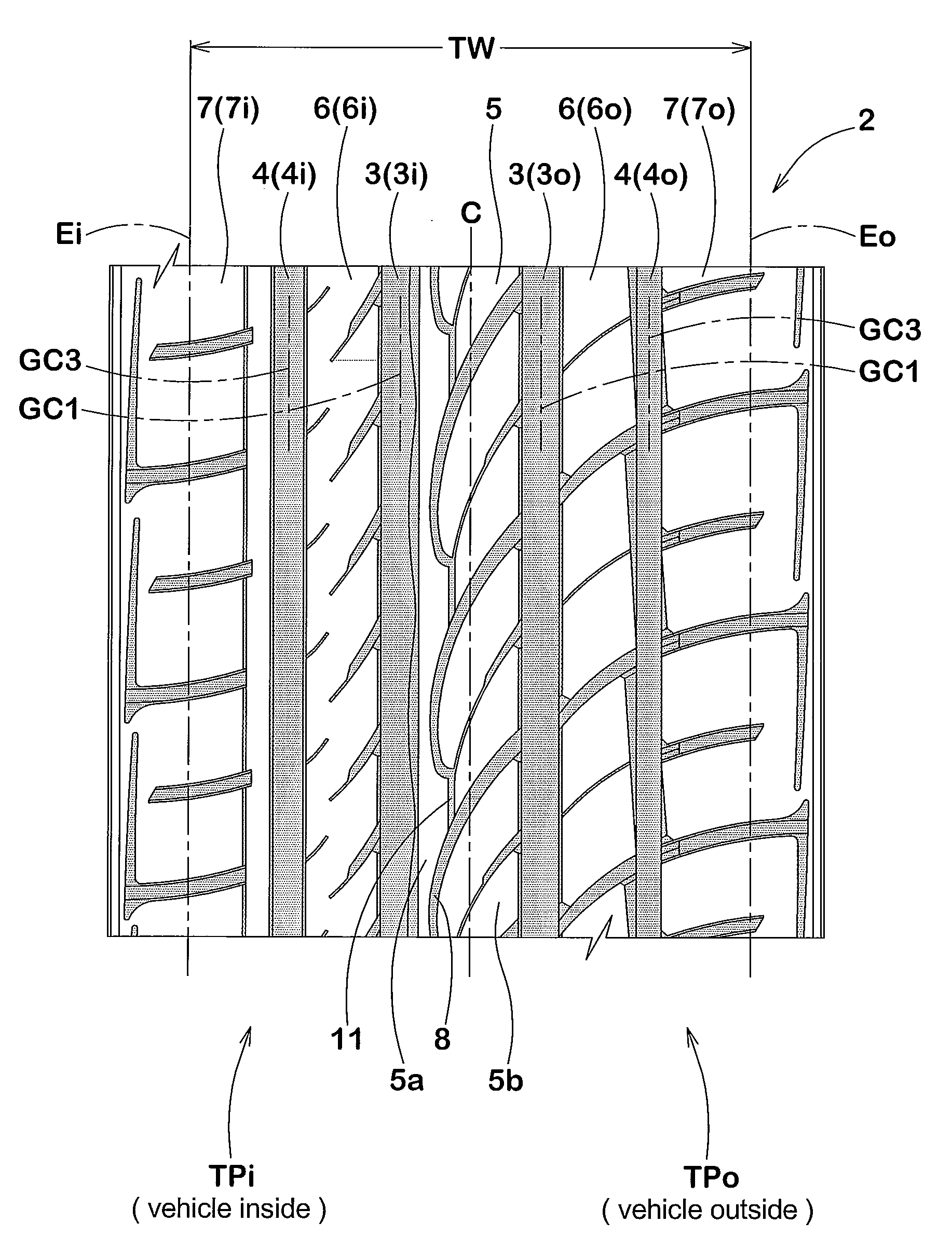
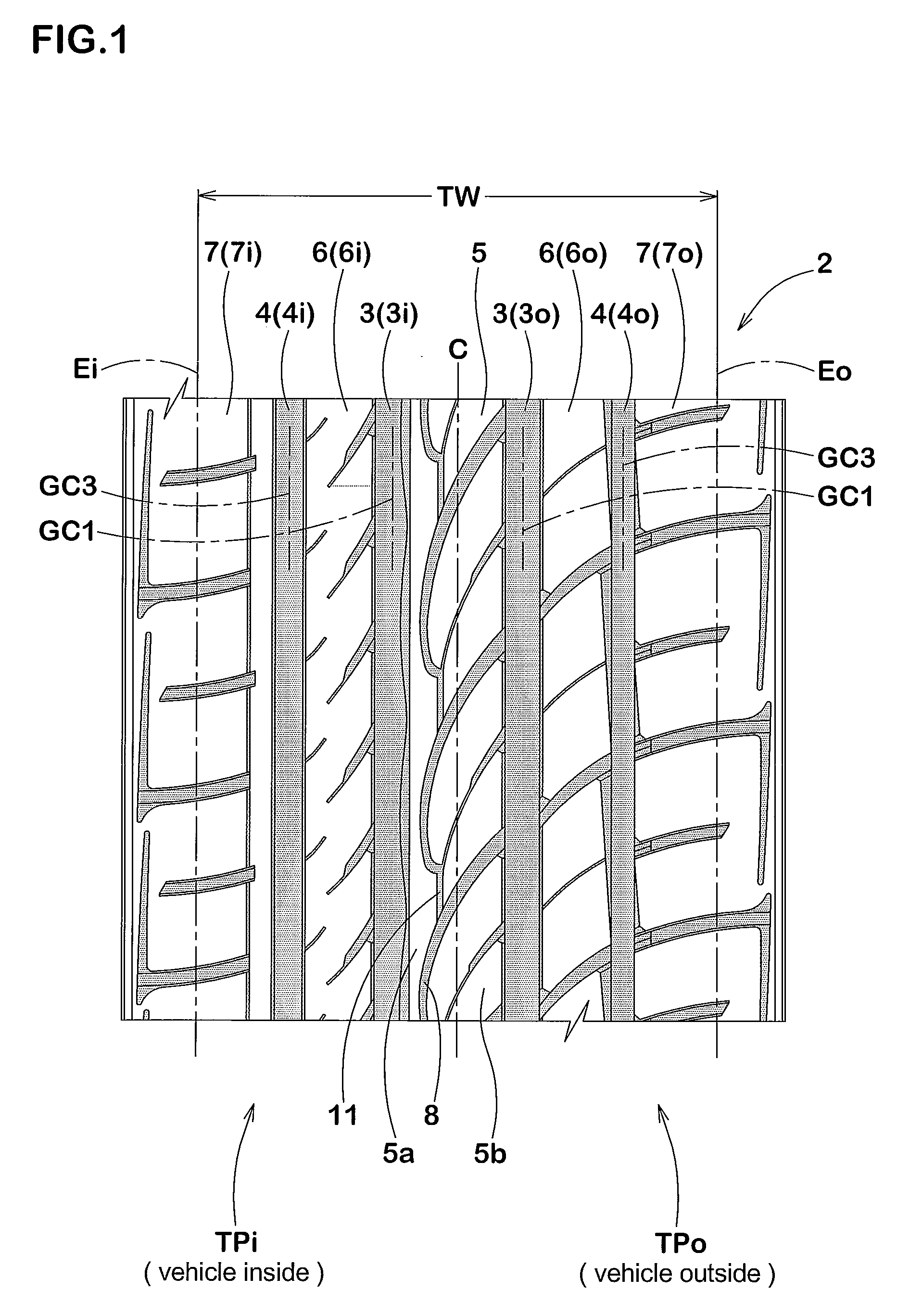
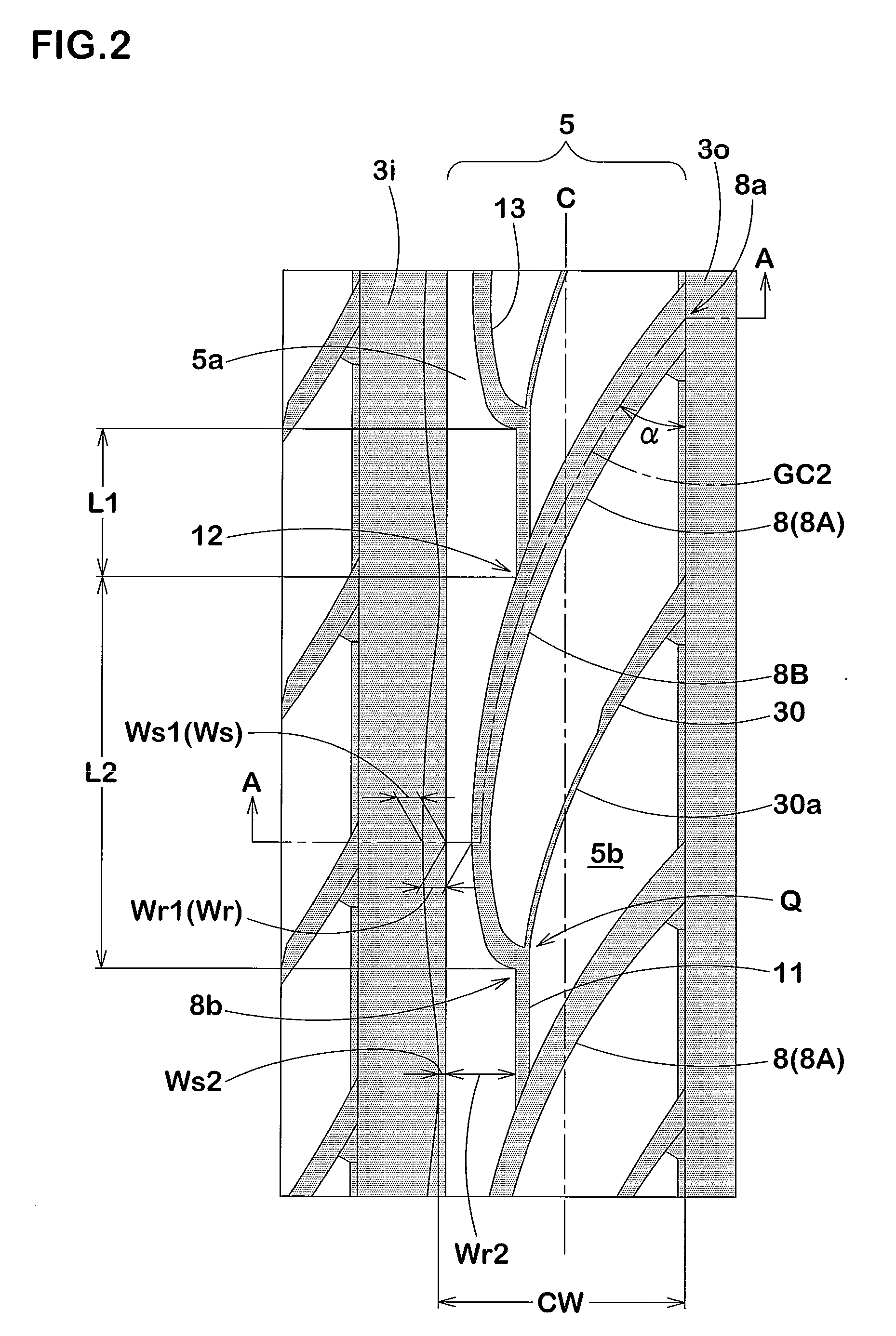
[0076]Pneumatic radial tires for passenger cars having a tire size of 225 / 45ZR17 and having a tread pattern shown in FIG. 1 were manufactured based on specifications shown in Table 1. The steering stability and drainage performance of the tires were tested. The results are shown in Table 1.[0077]Tread width: 185 mm[0078]Groove width of crown circumferential grooves: 12.9 mm[0079]Groove depth of crown circumferential grooves: 8.2 mm[0080]Groove width of shoulder circumferential grooves: 10.2 mm[0081]Groove depth of shoulder circumferential grooves: 8.2 mm[0082]Maximum groove width of curved oblique grooves: 5.7 mm[0083]Maximum depth of curved oblique grooves: 7.2 mm[0084]Maximum groove width of middle lateral grooves: 4.6 mm[0085]Maximum depth of middle lateral grooves: 7.2 mm[0086]Groove width of shoulder lateral grooves: 5.0 mm[0087]Maximum depth of shoulder lateral grooves: 6.5 mm[0088]Angle α at the outer end of curved oblique groove: 30°

[0089]The same test as above was also made...


PUM


Abstract

Steering stability and drainage property are improved in good balance. A center land portion 5 is formed between crown circumferential grooves 3i, 3o which are located on inner side and outer side of a vehicle and extend in the circumferential direction on both sides of the tire equator. In the center land portion 5 are disposed a plurality of curved oblique grooves 8 each of which extends obliquely toward the inner side of the vehicle across the tire equator from its outer end 8a opening at the outer crown circumferential groove 3o, turns toward the outer side of the vehicle, and further extends obliquely up to its inner end 8b located in the center land portion 5, and the respective curved oblique grooves 8 are connected with each other through connecting groove portions 11 each extending in the circumferential direction from the inner end 8b. In the center land portion 5 is disposed a center rib 5a which is defined by the connecting groove portions 11, portions of the curved oblique grooves 8 each portion extending between the connecting groove portions 11, and the inner crown circumferential groove 3i, and which extends continuously in the circumferential direction while repeating increase and decrease of its axial width, and the ratio of maximum width to minimum width of the center rib 5a is 2.0 to 4.0.

Description

TECHNICAL FIELD[0001]The present invention relates to a pneumatic tire having a steering stability and a drainage property which have been improved in good balance.BACKGROUND ART[0002]Pneumatic tires are required to have repugnant good properties, i.e., steering stability on dry asphalt roads and drainage property on wet roads. In order to simultaneously enhance these properties, a proposal is made in the following Patent Literature 1.Patent Literature 1: JP-A-2004-155416DISCLOSURE OF THE INVENTIONProblems To Be Solved By the Invention[0003]The Patent Literature 1 discloses a pneumatic tire wherein a sipe-like narrow circumferential groove is provided on the tire equator in a center rib extending on the tire equator. However, such a tread pattern leaves room for improvement in drainage property. On the other hand, in order to enhance the drainage property at a tire equator location, it is conceived to provide a wide straight groove on the tire equator. However, there is a possibilit...

Claims


Application Information

Patent Timeline
IPC IPC(8): B60C11/13B60C11/03
CPCB60C11/0309B60C11/0316B60C11/1369B60C11/1392B60C11/0304B60C2011/0374B60C2011/0369B60C2011/0388B60C2011/0383B60C2011/0381B60C11/1323
Inventor IWAI, YOSHITAKA
Owner SUMITOMO RUBBER IND LTD
Why Eureka
Try Eureka