Device for adjustment of pressure in tires

a technology for adjusting devices and tires, which is applied in the direction of tyre parts, transportation and packaging, packaging, etc., can solve the problems of difficult to keep in a vibrating tire, slow inflation, and high purchase cost of particular devices, so as to reduce the load of the chamber, eliminate centrifugal and disturbing forces, and increase the number of successful cycles of the chamber

Active Publication Date: 2010-12-30
CODA INNOVATIONS SRO
View PDF44 Cites 8 Cited by
  • Summary
  • Abstract
  • Description
  • Claims
  • Application Information

AI Technical Summary

Benefits of technology

[0019]Advantage of this solution, according to the invention is precisely defined length, volume, and location of the chamber. The solution according to the invention will further ensure proper inflating even in different temperatures of the tire in run and will unload the chamber from useless loading, where the chamber will only be loaded in moments when the tire is under-inflated, which decreases the load of the chamber and its wearing m the order of multiples of thousands. The chamber needs not fully close as in the previous solutions, which further increases the number of successful cycles of the chamber. The valve eliminates centrifugal and disturbing forces, thus further decreasing the risks of damage to the tire. The device is simple both for functioning and production, which determines its extreme reliability and low production and implementation costs.
[0020]The manufacture of this device is very simple; in its simplest configuration, it is only a simple valve fitted with an empty air-filled box with a membrane. Yet, it can be used to change the pressure as necessary, during assembly as well as in operation. The device is very simple and so its manufacture is inexpensive. Yet, it is reliable even under very difficult conditions of a rotating tire. The device can also provide right inflation even when pressure in the tire changes due to warming of the tire.

Problems solved by technology

Disadvantages of these solutions are extensive purchase costs and complexity of the particular device.
A disadvantage of these solutions is unsolved regulation, or, in case of setting the output pressure through the compression ratio in the chamber, a slow inflation.
For setting the output pressure through the chamber compression ratio, it is also disadvantageous to create the chamber along the whole tire perimeter as the chamber should be fully through-going, i.e. not loaded by deformation, at least once in a rotation.
To function properly, the peristaltic chamber needs to close gradually lengthwise in all its length, which is difficult to keep in a vibrating tire.
Thus the chamber and its parts are stressed extremely as this occurs a many million times during the tire life.
Also, these solutions do not deal with the difference caused by alteration in the tire pressure due to its heating, when the chamber output pressure corresponds to the desired pressure only if the tire temperature is identical with the set temperature of the tire.
Thus the chamber works only for a limited number of cycles and / or works and inflates inaccurately.
Movable mechanical parts are subject to the effects of centrifugal and other disturbing forces that moreover vary, which influences the accuracy of their behavior or can make the function of the device totally impossible or even cause a failure and destruction of the tire as such.
Further, in case the described circulation in the non-inflation period was not enabled there would be constant cyclic increase of pressure or under-pressure in the chamber, and thus also constant stressing and potential destruction.

Method used


Image

  • Device for adjustment of pressure in tires
  • Device for adjustment of pressure in tires
  • Device for adjustment of pressure in tires

Examples


example 1

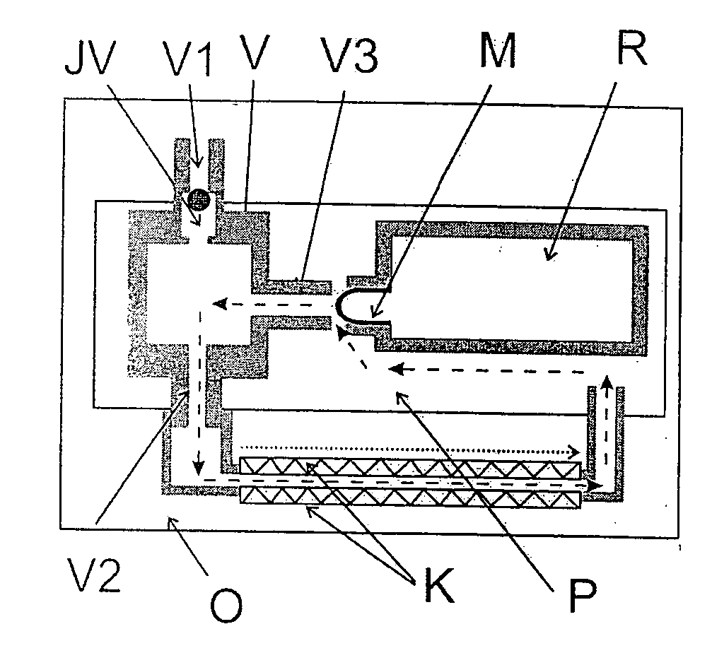
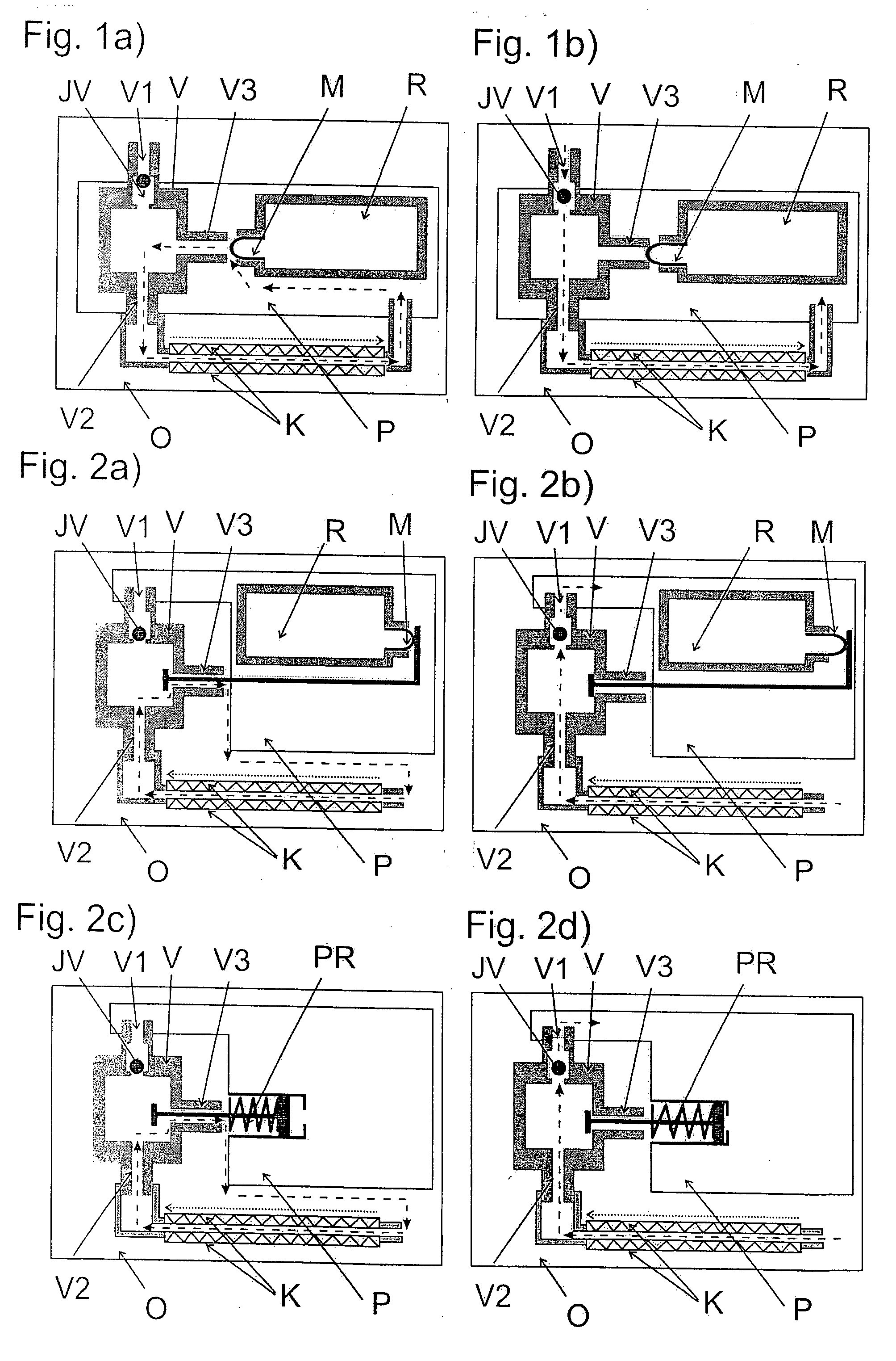
[0040]FIG. 1a shows the three-way valve V located in the tire internal space P. Its one input V1 is connected to the external environment O and is fitted with a one-way valve JV closed with a ball. Its second input V2 opens into the chamber with shape memory K, at the same time, the chamber K opens into the tire internal space P by its other end. The last input V3_of the three-way valve V opens into the tire internal space P, on this FIG. Further, the membrane M of the closure element R with reference pressure is placed against the last input V2[, on this fig. The membrane M is away from the last input V3; therefore this last input V3 is open. The closure element R with reference pressure is located inside the space P of the tire. In this case, the reference pressure inside the closure element R is equal to the desired pressure of the tire. The pressure of the tire internal space P is also at the set value; thus the volume of gas contained in the closure element R is being compresse...

example 2

[0042]FIG. 2a shows the three-way valve V located m the tire internal space P. Its one input V1 is connected to the tire internal space P and is fitted with a one-way valve JV closed with a ball. It is another input V2 opens into the chamber with shape memory K; at the same time, this chamber K opens into the external environment O with its other end. The last input V3_of the three-way valve V opens into the external environment O, on this FIG. Further, there is a tie rod in the last input V3 in this fig., with its seal controlled by the membrane M, closing the reference space of the closing element R; the seal is far away from this last input V3, therefore it is open. The reference space is located inside the tire internal space P. In this case, the reference pressure inside the closure element R is equal to the desired pressure of the tire. Pressure of the tire internal space P is also at the set value; thus the volume of gas contained in the reference space is compressed and the ...

example 3

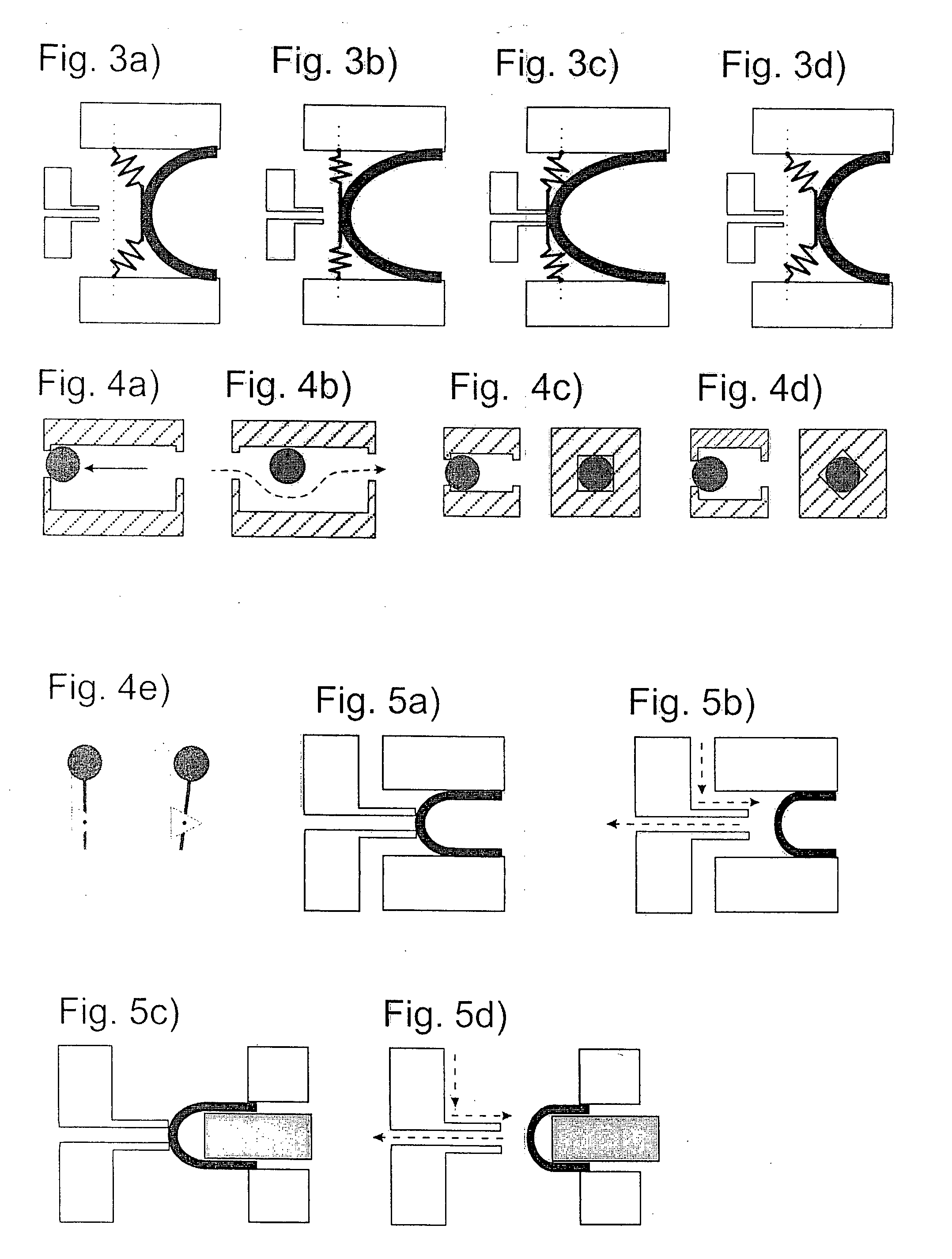
[0047]The rate of inflating depends on the ratio of the volume of chamber K to other parts, into which it presses the air, or parts, from which it draws the air out. Both the inner volume of the three-way valve V and the volume of the connection between the three-way valve V and the chamber K should be as small as possible. If it is not efficient or possible to make a short interconnection you can increase the rate of inflating by mounting an additional one-way valve DV between the three-way valve V and chamber K, see FIGS. 9a and 9b. This auxiliary one-way valve DV opens in the direction of the function of the chamber K and allows air circulation in the same way as shown in FIG. 1a, or 3a, respectively. In this case, however, after closing the last input V3_in every cycle the cyclic opening of the chamber K will be no longer able to ensure equalization of the pressure between the inside of the three-way valve V through the chamber K and the external environment O or the tire intern...


PUM


Abstract

A device for adjustment of pressure in tires includes a chamber with shape memory and a valve. The valve is a three-way valve with inputs interconnected with the external environment and the tire internal space, where one input is fitted with a valve, the next input is connected to one end of the chamber with shape memory, and the last input is interconnected with the closure element. The device for adjustment of pressure in tires includes the chamber with shape memory interconnected with the external environment through an input and with the tire chamber through an output and fitted with at least one valve. The length of the chamber in the direction of tire rotation equals 0.001 to 0.5 of the tire perimeter, where the volume of the chamber before deformation to volume of the chamber during deformation ratio is the same or higher then the desired tire pressure to pressure of the external environment ratio.

Description

BACKGROUND AND SUMMARY[0001]A device is described that adjusts the pressure in tires. The device consists of or comprises a chamber with shape memory, which is a part of the tire or adjacent to the tire wall, and of a valve. Eventually the device consists of or comprises a chamber with shape memory interconnected with the external environment through an input and with the tire chamber through an output, and fitted with at least one valve.[0002]Various solutions for refilling pressure in the tire are currently known. For example, it is a tire fitted with an air feed connected to an external pressure source. Disadvantages of these solutions are extensive purchase costs and complexity of the particular device.[0003]Self-reinflating tires arc known too. For instance, an exemplary self-reinflating tire is described in patent applications CZ PV 2002-1364 and CZ PV 2001-4451. The air feed chamber is located in the tire wall or next to it. With the tire deformation advancing by rolling the ...

Claims


Application Information

Patent Timeline
Patent Type & Authority Applications(United States)
IPC IPC(8): B60C29/02B60C29/04
CPCB60C29/06B60C23/12Y10T137/36B60C23/126B60C23/124B60C23/135
Inventor HRABAL, FRANTISEK
Owner CODA INNOVATIONS SRO
Why Eureka
Try Eureka