Rotary power tool operable in either an impact mode or a drill mode

a rotary power tool and impact mode technology, applied in the field of impact drivers, can solve the problems of unfavorable drilling operations, and general undesirable effects of impact drivers, and achieve the effects of less additional weight of tools, less impact drivers, and compact overall housings for tools

Inactive Publication Date: 2010-12-30
ROBERT BOSCH GMBH
View PDF32 Cites 31 Cited by
  • Summary
  • Abstract
  • Description
  • Claims
  • Application Information

AI Technical Summary

Benefits of technology

[0004]It is therefore an object of the present invention to provide a rotary power tool operable in either an impact mode or a drill mode which avoids the disadvantages of the prior art. The inventive rotary tool provides for a blocking member that is in either a first position wherein it blocks a hammer from moving axially along the rotational axis of the tool or a second position wherein it allows the hammer to move axially along the rotational axis of the tool and this determines whether the tool operates in drill mode or impact mode. Since the blocking member is supported by the driveshaft, the inventive rotary tool has the advantage that the blocking member can be quite compact versus the prior art, requiring little enlargement of the gearbox case and allowing a more compact overall housing for the tool. It is also advantageous that the blocking member is potentially lighter than prior art solutions and therefore may provide little additional weight to the tool.
[0005]The blocking member may move between the first and second positions by either moving axially or radially relative to the driveshaft. In certain cases, the blocking member may be arranged within a radial cavity in the driveshaft. Arranging the blocking member in a radial cavity of the driveshaft has the further advantage that the driveshaft can help support the axial load encountered by the blocking member, thereby requiring no additional design elements to be included for providing this function. These are simpler and more compact ways for determining the mode of operation of the tool than providing separate coaxial driveshafts for operating the tool in the different respective modes.
[0006]That the blocking member can be retained by a portion of the hammer rather than using an additional part or structure is a simple and cost-effective solution since no additional means for retaining the blocking member need to be constructed or positioned.
[0007]Adjustment of the position of the blocking member can be accomplished by movement of a sliding member which travels within an axial cavity in the driveshaft. This is advantageous since this arrangement requires no additional space in the tool for accommodating the sliding member. Compared to a solid driveshaft, the tool may advantageously be lighter than an alternative solution. Furthermore a recess in the same sliding member provides a simple and inexpensive way for the sliding member to interact with the blocking member so as to determine whether the blocking member is in a first position or a second position.
[0008]It is a simple solution to determine whether the sliding member is in the first or second sliding position by default by providing a biasing member to interact with the sliding member. For user-adjustment of the sliding member away from its default position, the tool is advantageously provided with an adjustment member, for example a rotatable sleeve, which the user can intuitively use to select between different positions of the sliding member and therefore different modes of operation. As such the user can adjust the modes without disassembling the tool. It is simpler and more economical to combine the mode-selection function provided by the rotatable sleeve with other functions, such as adjustment of the rotational speed of the driveshaft.
[0009]The mode switching function can also be embodied in a standalone attachment for a power tool. The user can advantageously use such an attachment on a rotary tool that does not have the impact function and still retain the conventional drill function without removing the attachment.

Problems solved by technology

When high resistance to rotation is encountered, the anvil may slow or halt altogether.
Because it may damage screws or bits not intended for bursts of high torque, an impact driver is generally considered undesirable for low torque applications, and a typical user may be obliged to carry with him a more conventional drill for these purposes.
Since the devices operate so similarly, it may seem especially undesirable that one should have to purchase, maintain, and make use of two distinct tools where one might suffice.
A disadvantage of existing hybrid designs is that they are bulky and / or heavy since the housing must accommodate means for achieving all modes.

Method used


Image

  • Rotary power tool operable in either an impact mode or a drill mode
  • Rotary power tool operable in either an impact mode or a drill mode
  • Rotary power tool operable in either an impact mode or a drill mode

Examples


Embodiment Construction

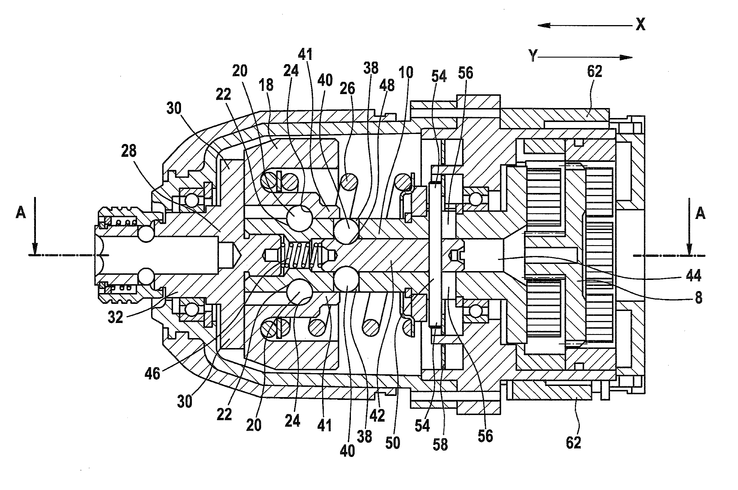
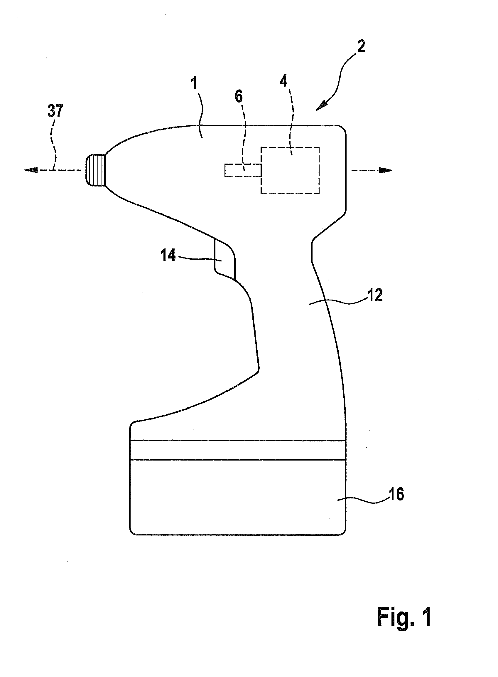
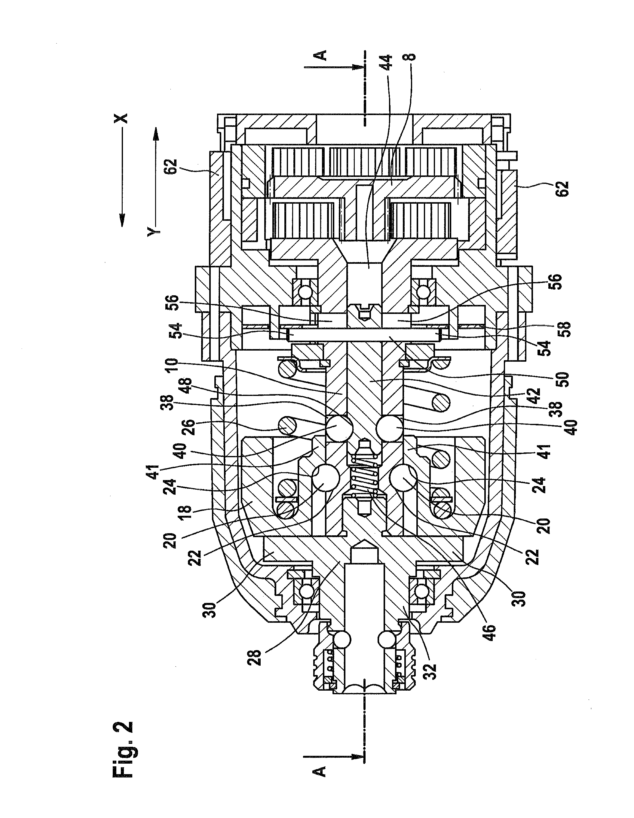
[0022]An example of a rotary tool according to the present invention is illustrated in FIG. 1. Within a housing 1 of an impact driver 2 is a motor 4 and an associated motor shaft 6. Rotation of the motor shaft 6 is transduced via various step down planetary gears in a gearbox 8 to rotate a driveshaft 10. The tool is provided with a handle 12 and a trigger 14 so that it may be conveniently operated by a user. A battery 16 provides a DC power source but an AC power source is a standard alternative.

[0023]While still further modes are possible, the impact driver 2 may operate in at least two different modes: impact mode and drill mode. In impact mode, the tool operates as is customary for an impact driver, providing intermittent impacts to the output shaft when high torque is required. As will be described in the subsequent description, in drill mode the impact function is disabled and the tool operates much like a standard drill / driver. A comparable impact driver 2 representing the pre...


PUM

PropertyMeasurementUnit
torqueaaaaaaaaaa
rotational speedaaaaaaaaaa
rotationaaaaaaaaaa

Abstract

A rotary power tool operable in either an impact mode or a drill mode comprising a driveshaft (10), an output shaft (32), a hammer (18) coupled to the driveshaft (10) for transmitting torque to the output shaft (32), and a blocking member (40, 74) which is in a first position wherein it blocks the hammer (18) from moving axially along the rotational axis (37) of the tool when the power tool operates in the drill mode and is in a second position wherein it allows the hammer (18) to move axially along the rotational axis (37) of the tool when the power tool operates in the impact mode, wherein the blocking member (40, 74) is supported by the driveshaft (10).

Description

PRIOR ART[0001]The present invention relates to impact drivers, a category of rotary power tools intended for use in high torque driving applications. Pulses of torque are generated in such tools via a hammer and anvil arrangement mounted between the driveshaft and output shaft.[0002]A typical arrangement is shown in US Patent Publication No. 2006 / 0237205 A1. A driveshaft is coupled to a hammer so that rotation of the driveshaft normally rotates the hammer. The hammer contacts an anvil that is integral with an output shaft. When the output shaft encounters little resistance, the anvil rotates along with the hammer. When high resistance to rotation is encountered, the anvil may slow or halt altogether. However the coupling of the hammer to the driveshaft is such that the hammer will repeatedly draw away from the anvil and then spin forward with increased velocity to strike the anvil and provide a pulse of torque, this impact occurring as many as two times per revolution of the drives...

Claims


Application Information

Patent Timeline
Patent Type & Authority Applications(United States)
IPC IPC(8): B23B45/16
CPCB25B21/026B25B21/00
Inventor LEONG, CHI HOEWAN, MOHSEINLEE, SIEW YUENLUTZ, MANFRED
Owner ROBERT BOSCH GMBH
Why Eureka
Try Eureka