Vehicle With Contactless Throttle Control

Active Publication Date: 2010-12-30
GP TECH & INNOVATION LTD
View PDF9 Cites 14 Cited by
  • Summary
  • Abstract
  • Description
  • Claims
  • Application Information

AI Technical Summary

Benefits of technology

[0015]The present invention thus provides an improved vehicle power control that can allow, for example, improved reliability and stab

Problems solved by technology

Throttle controls that rely on contact between an manipulable portion and a potentiometer or other throttle position-sensing d

Method used


Image

  • Vehicle With Contactless Throttle Control
  • Vehicle With Contactless Throttle Control
  • Vehicle With Contactless Throttle Control

Examples


Example

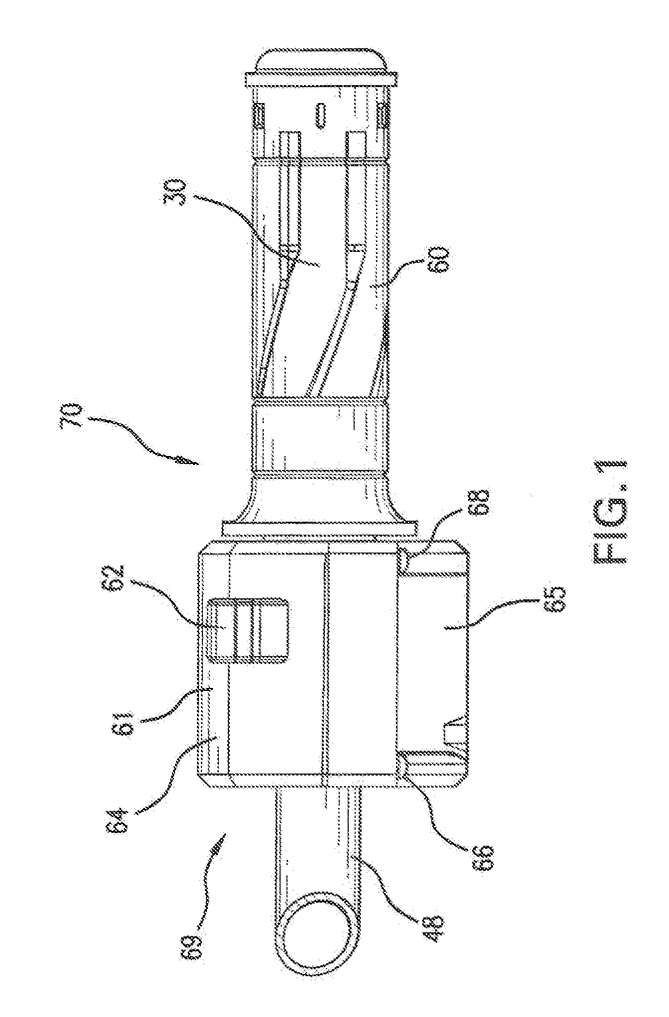
[0025]Referring to FIG. 1, a preferred embodiment of a vehicle power control 70 includes a throttle mounting portion and a throttle. The throttle mounting portion 69 includes a handle bar 48 on which the throttle housing 61 is mounted. Throttle housing 61 preferably includes an upper housing 64 and a lower housing 65, which are preferably fastened together, such as by fastener 66 and 68. An emergency kill switch 62 is disposed on the throttle housing 61, accessible for operation preferably with a rider's thumb, but can alternatively be disposed in other locations. A grip 60 is mounted on the throttle 30 (see FIG. 2) to allow for easy grasping and rotation of the throttle. A grip 60 is mounted on the throttle 30 to allow for easy grasping and rotation of the throttle. Preferred grip 60 is made from an elastomer material, although other materials can be used as known in the art.

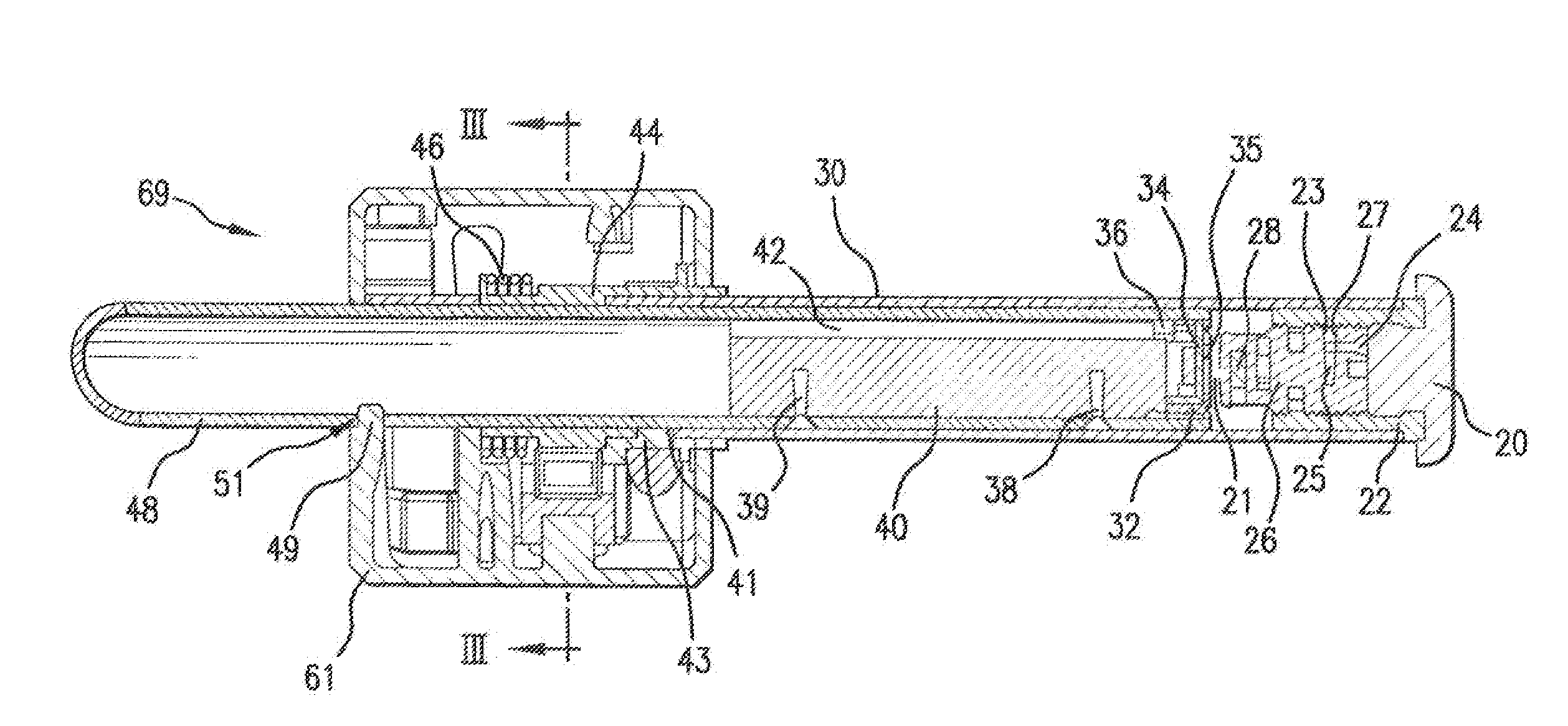
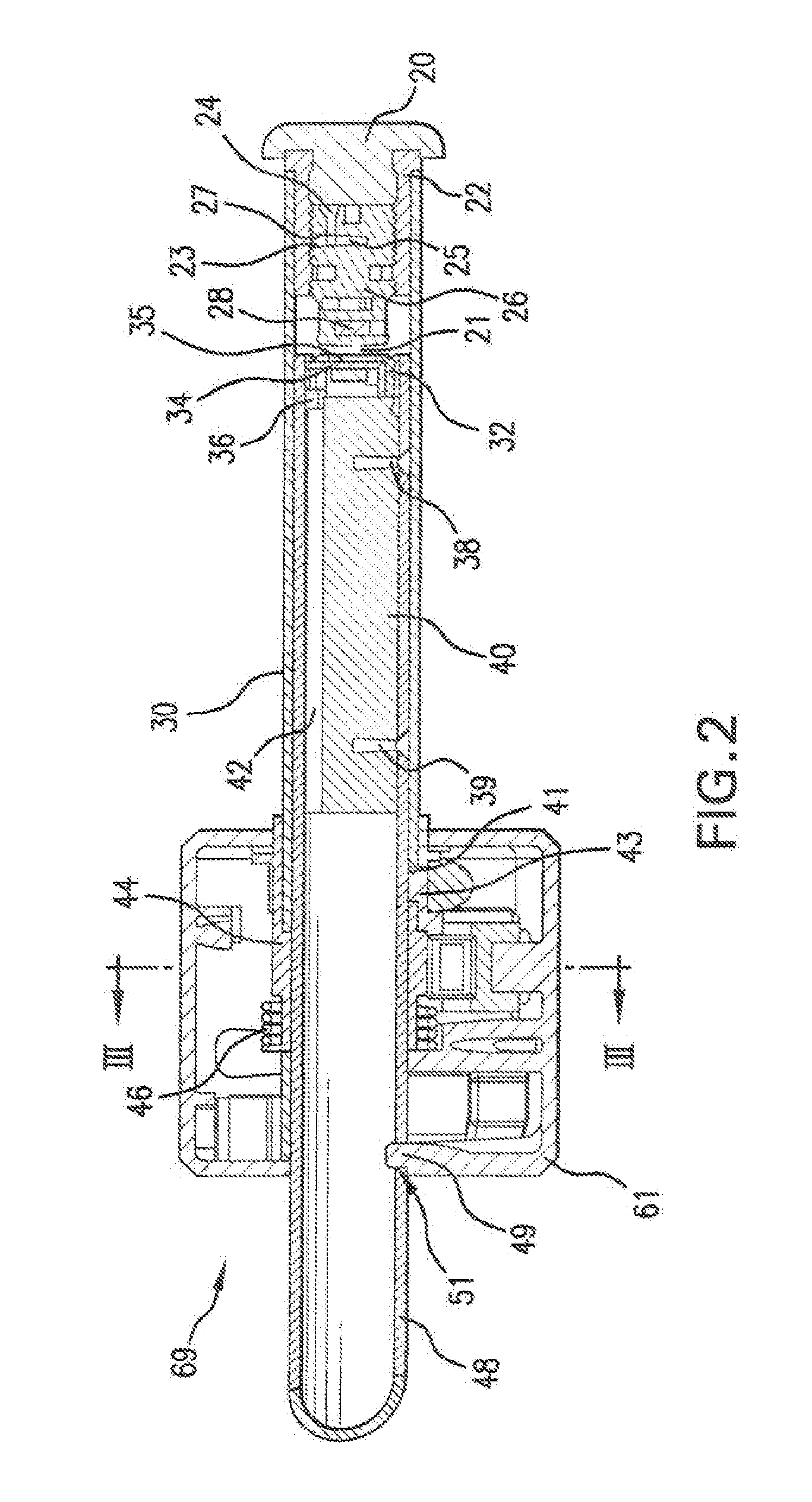
[0026]As shown in FIG. 2, sleeve 22 is preferably fixed within throttle 30, and is threaded internally. Magn...


PUM


Abstract

A vehicle power control that includes a throttle mounting portion and a throttle that is movably mounted to the throttle mounting portion and configured for manipulation and operation by a rider. The power control also includes a sensor in contactless association with at least one of the throttle and throttle mounting portion. The sensor is configured for sensing a position of the throttle with respect to the mounting portion, in the contactless association, and generating a signal based on the sensed position for controlling motive power of a vehicle.

Description

CROSS-REFERENCE TO RELATED APPLICATION[0001]This application is a continuation of U.S. patent application Ser. No. 11 / 762,596 filed Jun. 13, 2007 which is a continuation of PCT / US07 / 70980 filed Jun. 12, 2007, which claims the benefit of provisional application No. 60 / 813,364, filed on Jun. 14, 2006, which are hereby incorporated herein by reference.FIELD OF THE INVENTION[0002]The present invention relates generally to a control for powering a vehicle, and more particularly, a contactless vehicle power control.BACKGROUND OF THE INVENTION[0003]Vehicles are known with throttle controls that are mechanical and electrical. An example of an electrical throttle control is in U.S. Pat. No. 6,581,714, which describes a steering control of a personal transporter, where the steering device uses a potentiometer coupled to the handlebar for generating a steering command upon rotation. U.S. Pat. No. 6,724,165 discloses a vehicle that uses a potentiometer as means of producing control command. In ...

Claims


Application Information

Patent Timeline
IPC IPC(8): B60K26/02
CPCB60L7/16B60L11/1809Y02T90/14B62K23/04Y02T10/7005B60L2200/12B60L53/00Y02T10/70Y02T10/7072
Inventor DUGAS, DAVIDBLISS, CRAIGHUGHES, PETER S.
Owner GP TECH & INNOVATION LTD
Why Eureka
Try Eureka