

Combustion chamber and cooling system for fastener-driving tools
- Summary
- Abstract
- Description
- Claims
- Application Information
AI Technical Summary
Benefits of technology
Problems solved by technology
Method used
Image

Examples
Embodiment Construction
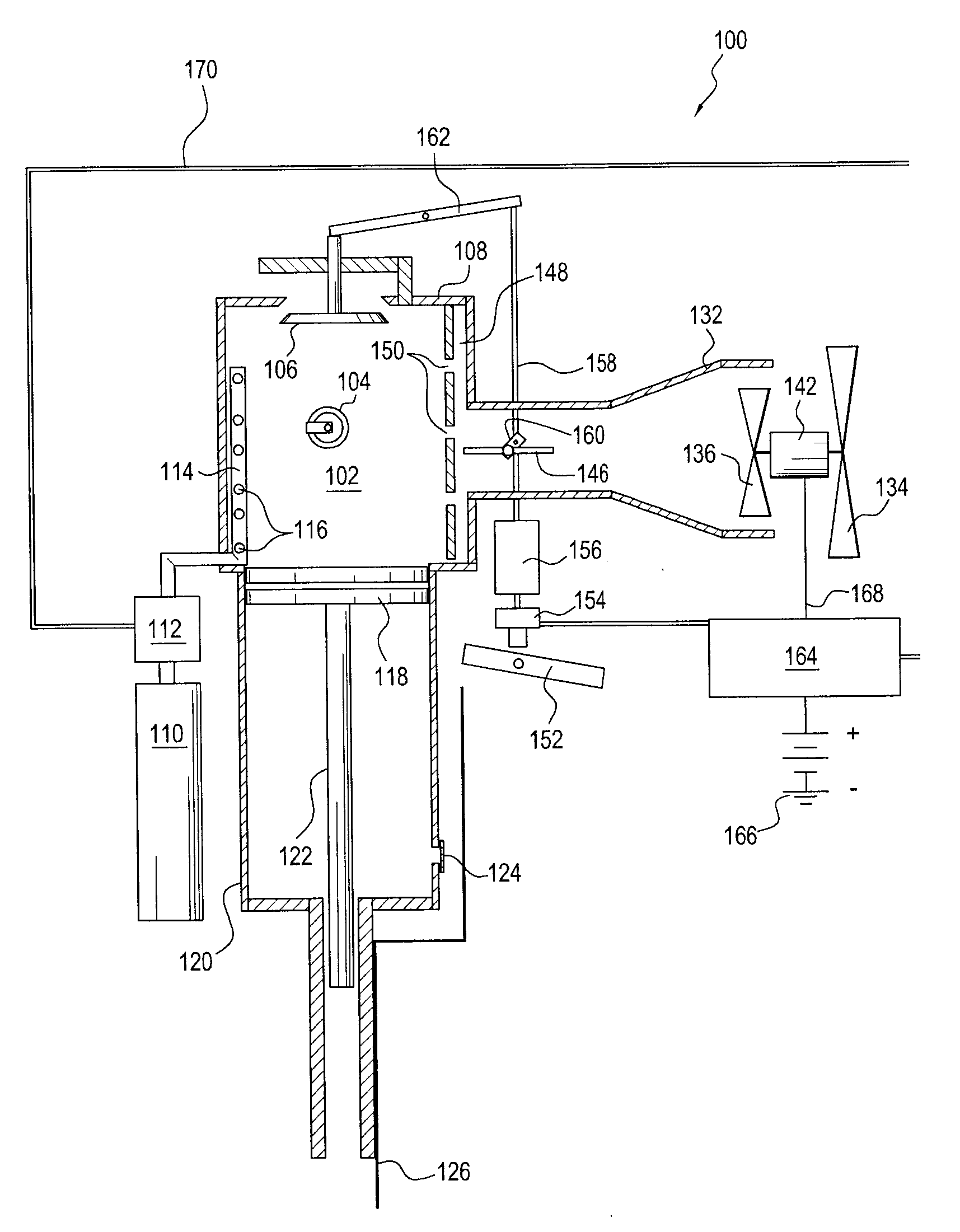
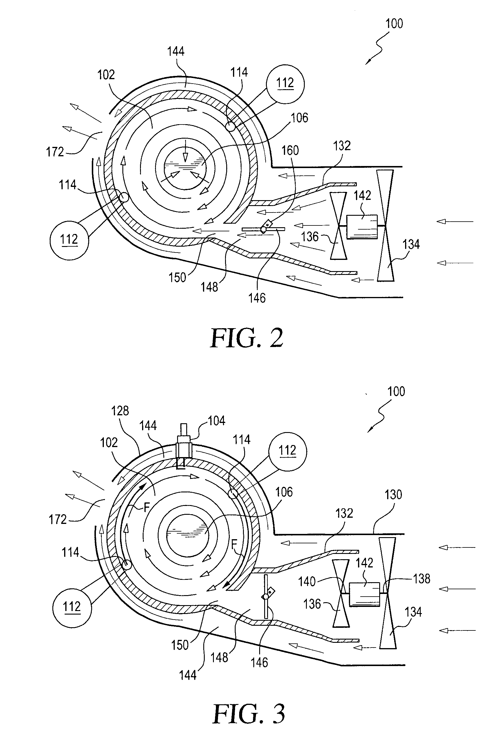
[0016]Referring now to the drawings, and more particularly to FIGS. 1-3 thereof, a first embodiment of a new and improved fastener-driving tool, as constructed in accordance with the principles and teachings of the present invention and showing the cooperative parts thereof, is disclosed and is generally indicated by the reference character 100. More particularly, it is seen that the first embodiment of the new and improved fastener-driving tool 100 comprises a combustion chamber 102 having an ignition device, such as, for example, a spark plug 104 disposed within a side wall portion thereof, and an exhaust scavenging valve 106 which is reciprocally movable in the vertical direction with respect to the upper wall member 108 of the combustion chamber 102 so as to be movable between an opened position and a closed position. In addition, the fastener-driving tool 100 is provided with one or more fuel supplies 110, one or more fuel injectors 112 fluidically connected to the one or more ...
PUM
 Abstract
Description
Claims
Application Information