Device for reducing jet engine exhaust noise using oscillating jets

Active Publication Date: 2005-07-07
GENERAL ELECTRIC CO
View PDF24 Cites 6 Cited by
  • Summary
  • Abstract
  • Description
  • Claims
  • Application Information

AI Technical Summary

Benefits of technology

[0005] In an embodiment, oscillating jets are placed at a trailing edge lip of a jet aircraft engine exhaust nozzle to enhance the mixing of jet engine exhaust. An oscillating jet, which can also be referred to as a flip-flop jet, is a passive system in the engine exhaust system. The oscillating jet has a nozzle with a triangular shaped orifice and an exhaust pipe, through which the stream of mixing gas passes. The oscillating jet introduces an oscillating stream of a gas into the engine exhaust. The oscillating stream of gas interacts with the jet engine exhaust shear layers and enhances the mixing of the engine exhaust shear layers. This mixing creates a fluidic chevron, whi

Problems solved by technology

However, these methods are not without their disadvantages.
However, these methods typically result in engine performance penalties, including thrust reduction and adverse effects on specific fuel consumption.
These penalties are compounded by the fact that these mecha

Method used


Image

  • Device for reducing jet engine exhaust noise using oscillating jets
  • Device for reducing jet engine exhaust noise using oscillating jets
  • Device for reducing jet engine exhaust noise using oscillating jets

Examples


Example

[0014] The present invention will be explained in further detail by making reference to the accompanying drawings, which do not limit the scope of the invention in any way.

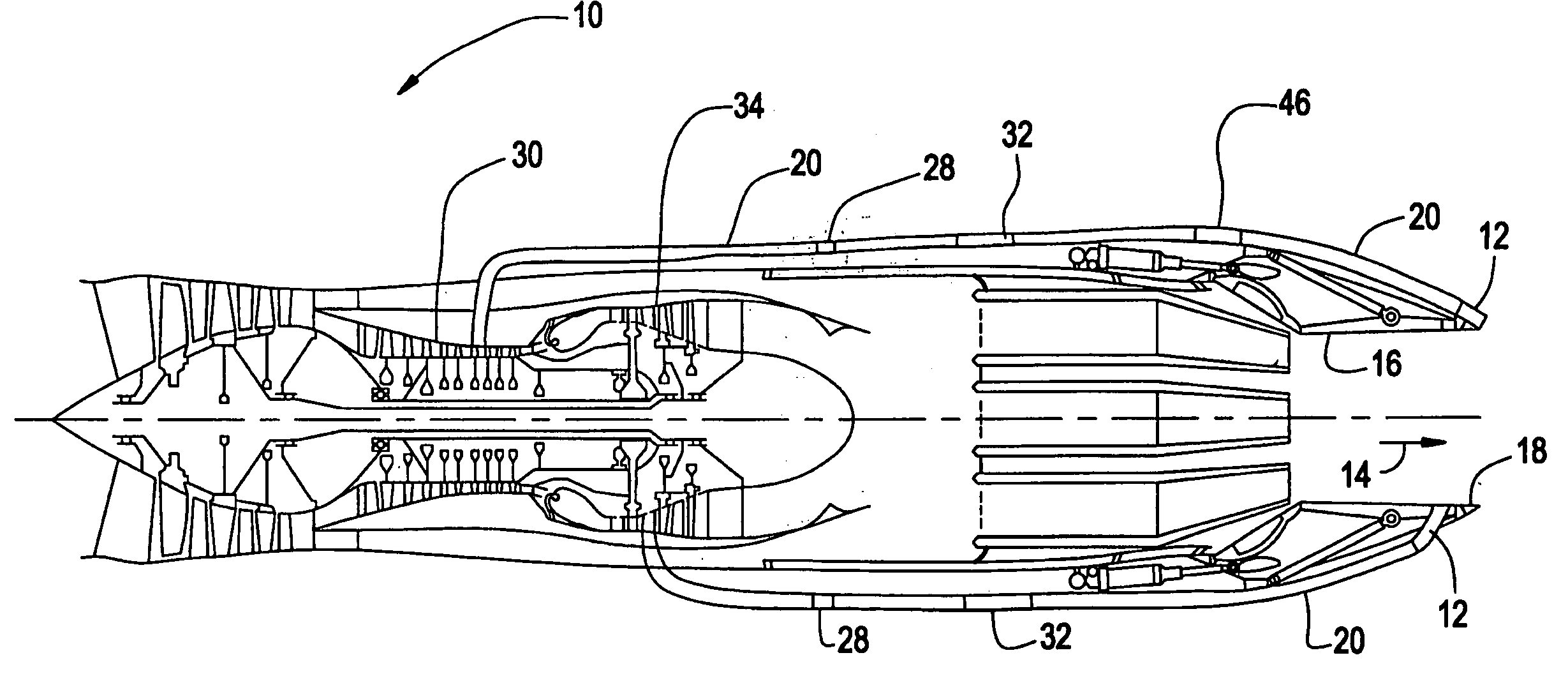
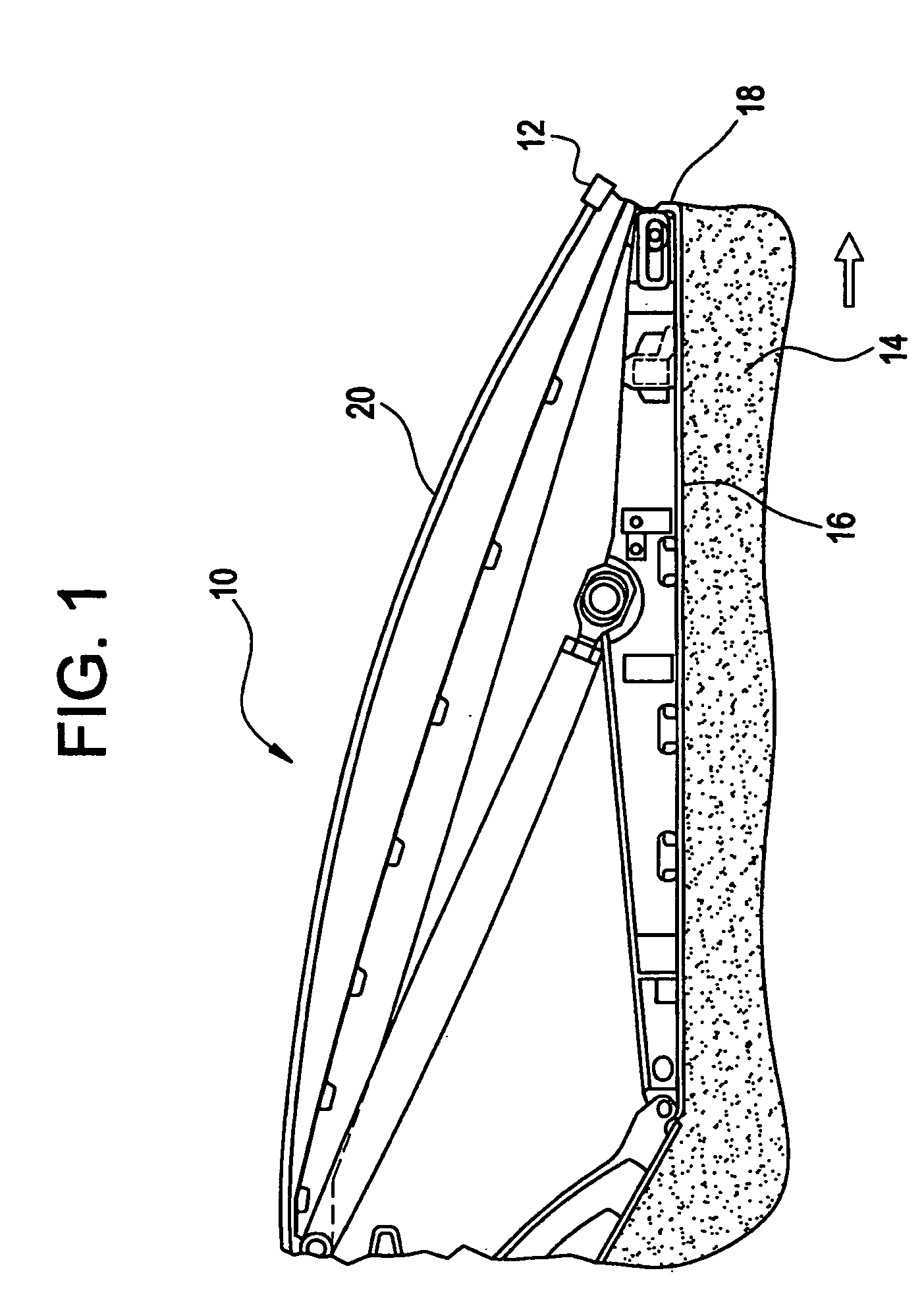
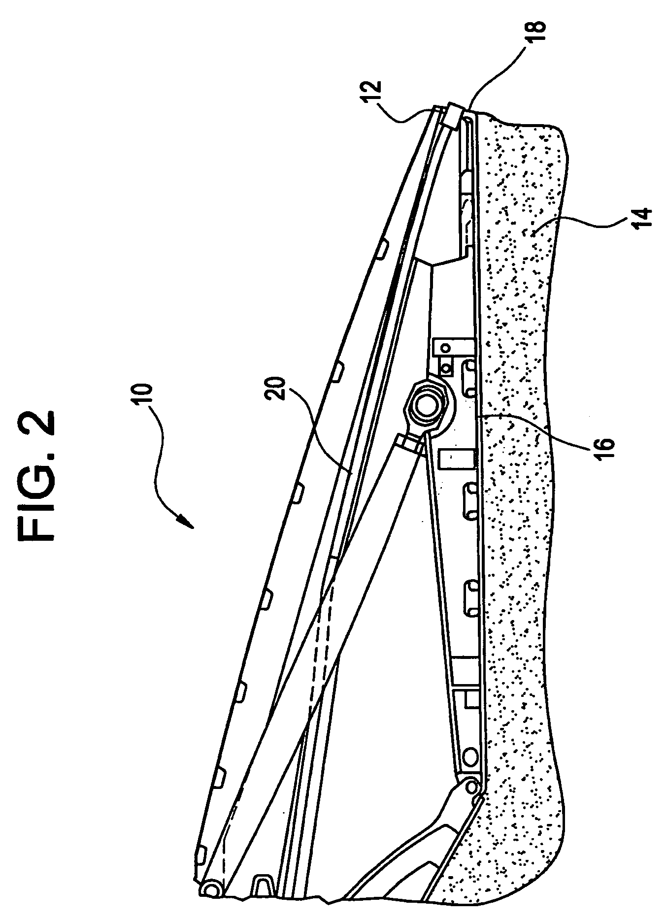
[0015]FIG. 1 is a cross-sectional side view of a portion of a jet aircraft engine 10 including an oscillating jet 12, positioned according to an embodiment of the invention. FIG. 2 is a cross-sectional side view of a portion of a jet aircraft engine 10 including an oscillating jet 12, positioned according to another embodiment of the invention. FIG. 3 is a cross-sectional side view of a portion of a jet aircraft engine 10, similar to that shown in FIG. 1, where a flow control valve is located upstream of the oscillating jet 12. FIG. 4 shows an aircraft engine 10 with an oscillating jet 12 positioned in the exhaust portion 16 of the engine 10. FIG. 5 is an asymmetric, cross-sectional view of an oscillating jet 12, and FIG. 6 is a lateral cross-sectional view of an oscillating jet 12.

[0016] In the jet aircraft eng...


PUM


Abstract

A device for reducing engine exhaust noise in an aircraft engine includes a number of oscillating jets which direct an oscillating flow into the engine exhaust. The oscillating jets are connected via channels to a turbomachinery source of high pressure gas, where the source is located upstream from the engine exhaust portion. The high pressure gas passes through the oscillating jets, which have a nozzle with a triangular shaped orifice and an exhaust pipe, and exits the oscillating jets having a oscillating flow. The oscillating flow mixes with the engine exhaust thus reducing the noise created by the engine exhaust.

Description

BACKGROUND OF THE INVENTION [0001] This invention relates to an apparatus for reducing jet engine exhaust noise, and more particularly to using oscillating jets to reduce jet engine exhaust noise. [0002] The reduction of engine noise generated by jet aircraft engines is becoming an important aspect of jet engine design. This is true in both commercial and military applications, where the reduction of noise has obvious benefits. Additionally, the reduction of noise is beneficial to increasing the operational life of a jet engine and engine components because noise can contribute to the wear and sonic fatigue of engine components. [0003] Various methods have been developed to decrease jet aircraft engine noise. However, these methods are not without their disadvantages. For example, chevrons and other geometric modifications have been employed in engine exhaust systems to enhance the mixing of the jet engine exhaust flow to reduce noise. However, these methods typically result in engi...

Claims


Application Information

Patent Timeline
IPC IPC(8): F02K1/12F02K1/34F02K1/28
CPCF02K1/1292F02K1/34F05D2250/11F05D2260/96Y02T50/671Y02T50/60
Inventor GUPTA, ANURAG
Owner GENERAL ELECTRIC CO
Why Eureka
Try Eureka