Reference voltage generator having a two transistor design

a reference voltage and transistor technology, applied in the direction of electric variable regulation, process and machine control, instruments, etc., to achieve the effect of reducing the power consumption of the generator, improving performance, and affecting the temperature sensitivity of vr

Active Publication Date: 2010-12-30
RGT UNIV OF MICHIGAN
View PDF9 Cites 20 Cited by
  • Summary
  • Abstract
  • Description
  • Claims
  • Application Information

AI Technical Summary

Benefits of technology

[0024]During operation, the gate-source voltages of the first transistor M1 and the second transistor M2 must be set to ensure that both transistors are operated in a weak inversion operating mode (also commonly referred to as a subthreshold region). By operating the transistors in a weak inversion mode (rather than in a saturation region), power consumption of the generator is reduced dramatically as compared to existing designs. Furthermore, operation in a weak inversion mode ensures that the voltage reference generator can operate with supply voltage (VDD) much less than 1V. For improved performance, the drain-source voltages on M1 and M2 should be greater than approximately 3vT, where vT is the thermal voltage. Combining these assumptions with a well-known subthreshold current equation shows that the value of the reference voltage VREF is:
[0025]Through transistor sizing, the temperature dependence of VREF can be changed from proportional-to-absolute temperature (PTAT) to complementary-to-absolute temperature (CTAT) to temperature-independent. In a typical implementation, the gate width of transistor M1 would be chosen relative to the gate width of transistor M2 to make VREF insensitive to temperature. In addition to affecting the temperature sensitivity of VREF, the gate sizes of transistor M1 and transistor M2 affect the power consumption of the voltage reference generator. For example, choosing transistors M1 and M2 to have narrow width or long length would reduce the power consumption of the voltage reference generator substantially.
[0026]Since coupling though the parasitic MOSFET capacitance can affect power supply rejection ratio, an output capacitor may be added for signal robustness. Larger output capacitance provides a better power supply rejection ratio.

Problems solved by technology

Voltage references are commonly integrated in wireless sensing systems with tight power budgets, which are often less than hundreds of nanowatts due to very limited energy sources.

Method used


Image

  • Reference voltage generator having a two transistor design
  • Reference voltage generator having a two transistor design
  • Reference voltage generator having a two transistor design

Examples


Embodiment Construction

[0020]Example embodiments will now be described more fully with reference to the accompanying drawings. Example embodiments are provided so that this disclosure will be thorough, and will fully convey the scope to those who are skilled in the art. Numerous specific details are set forth such as examples of specific components, devices, and methods, to provide a thorough understanding of embodiments of the present disclosure. It will be apparent to those skilled in the art that specific details need not be employed, that example embodiments may be embodied in many different forms and that neither should be construed to limit the scope of the disclosure.

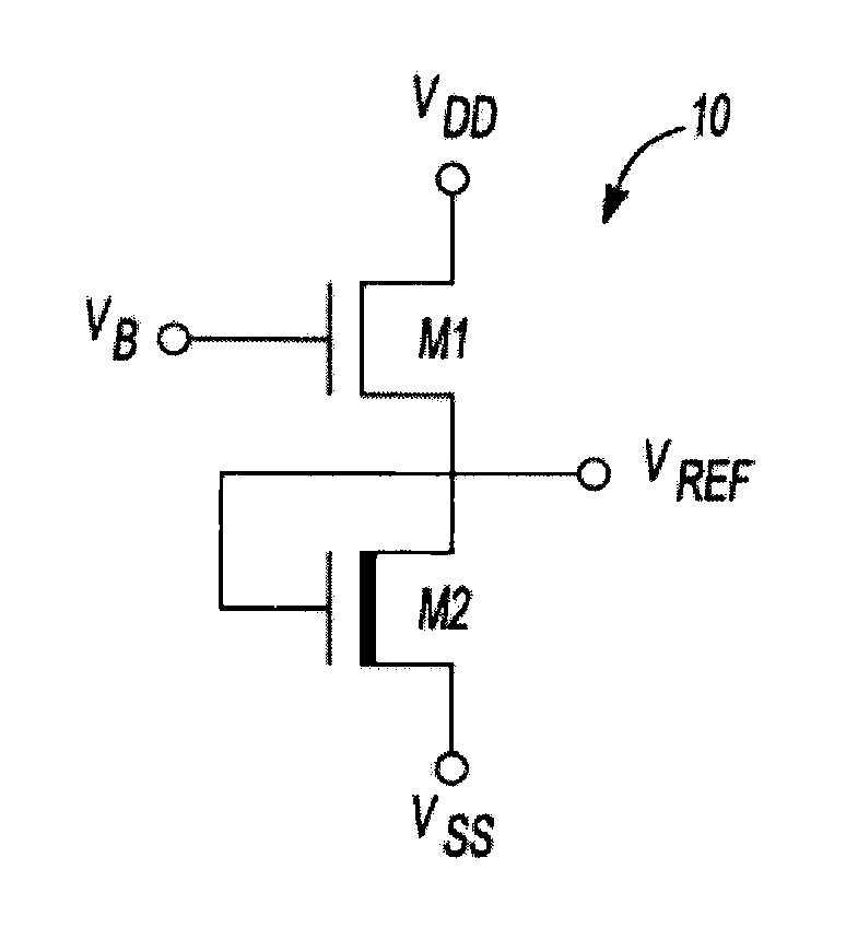
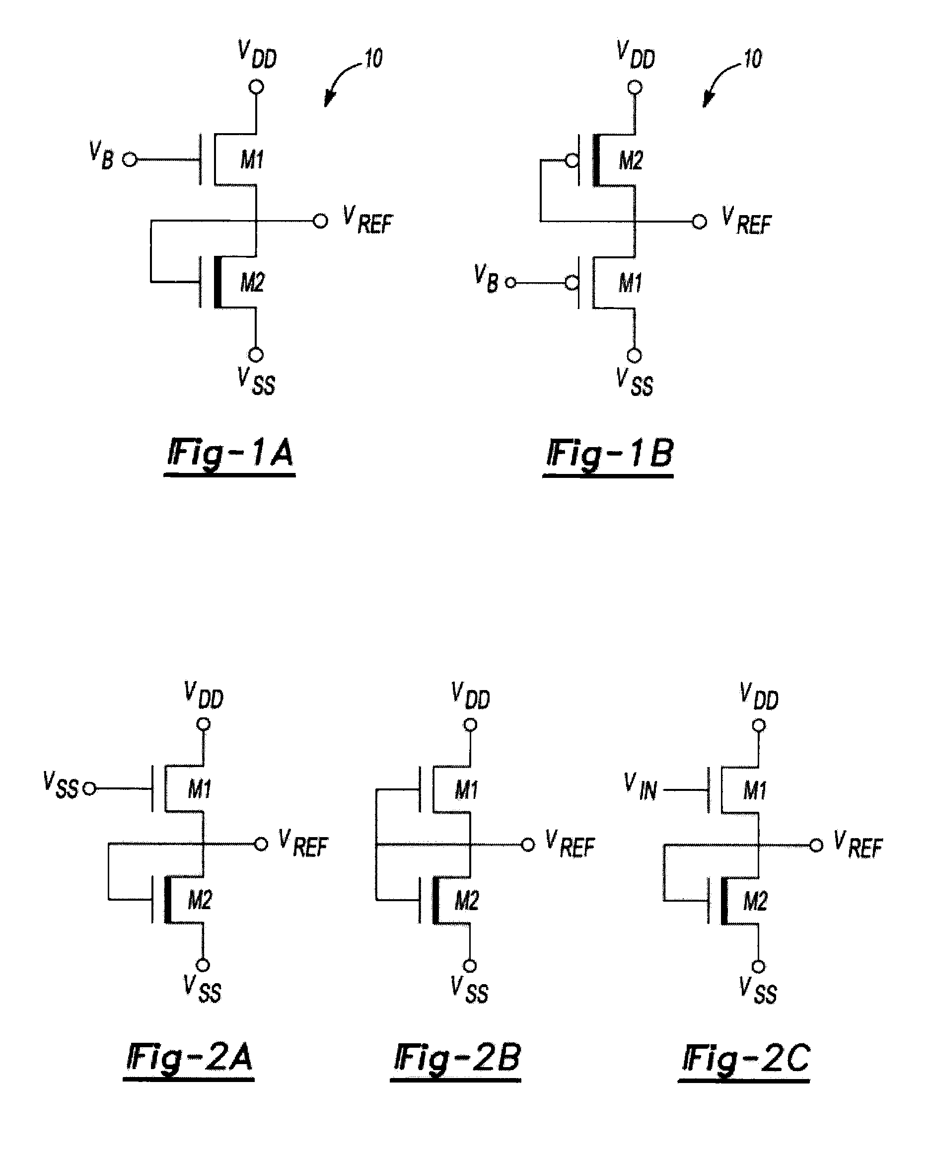
[0021]FIGS. 1A and 1B illustrate a basic circuit structure for an improved voltage reference generator 10 according to the principles of this disclosure. The voltage reference generator 10 is comprised of two transistors M1 and M2 connected in series between a supply voltage (VDD) and a ground voltage (VSS). Both VDD and VSS may be tra...


PUM


Abstract

An improved voltage reference generator is provided. The voltage reference generator comprises: a first transistor having a gate electrode biased to place the first transistor in a weak inversion mode; and a second transistor connected in series with said first transistor and having a gate electrode biased to place the second transistor in a weak inversion mode, where the threshold voltage of the first transistor is smaller than the threshold voltage of the second transistor and the gate electrode of the second transistor is electrically coupled to a drain electrode of the second transistor and the source electrode of the first transistor to form an output for a reference voltage.

Description

CROSS-REFERENCE TO RELATED APPLICATIONS[0001]This application claims the benefit of U.S. Provisional Application No. 61 / 220,712 filed on Jun. 26, 2009. The entire disclosure of the above application is incorporated herein by reference.GOVERNMENT INTEREST[0002]This invention was made with government support under Grant No. EEC9986866 awarded by the National Science Foundation. The government has certain rights in the invention.FIELD[0003]The present disclosure relates to an improved reference voltage generator that improves power consumption, size and ease of design with comparable temperature, supply voltage and process insensitivity to existing designs.BACKGROUND AND SUMMARY[0004]Recent progress in ultra-low power (ULP) circuit design has been made due to significant interest in environmental and biomedical sensor applications. These systems often include analog and mixed-signal modules such as linear regulators, A / D converters, and RF communication blocks for self-contained functi...

Claims


Application Information

Patent Timeline
Patent Type & Authority Applications(United States)
IPC IPC(8): G05F3/16
CPCG05F3/242
Inventor SEOK, MINGOOSYLVESTER, DENNISBLAAUW, DAVIDHANSON, SCOTTCHEN, GREGORY
Owner RGT UNIV OF MICHIGAN
Why Eureka
Try Eureka