Construction machine

a construction machine and construction technology, applied in mechanical equipment, machines/engines, separation processes, etc., can solve the problems of deteriorating workability high time and trouble required in the cleaning operation of the particulate matter removing filter, and the obstruction of the pressure sensor and the pressure conduit, so as to facilitate the maintenance operation of the filter

Active Publication Date: 2011-01-06
NIHON KENKI CO LTD
View PDF8 Cites 43 Cited by
  • Summary
  • Abstract
  • Description
  • Claims
  • Application Information

AI Technical Summary

Benefits of technology

[0011]In view of the above-described problems with the prior art, it is an object to provide a construction machine in which, even if the pressure sensor and the pressure conduits are provided in the vicinities of the exhaust gas purifying device, only the filter cylinder can be easily mounted and dismounted without moving the upstream cylinder and the downstream cylinder, to thereby facilitate the maintenance operation of the filter within the filter cylinder.

Problems solved by technology

For this reason, there is a problem in that much time and trouble are required in the cleaning operation of the particulate matter removing filter.
However, in the case where the pressure sensor and the pressure conduits are mounted on the upper side of the exhaust gas purifying device, the pressure sensor and the pressure conduits serve as obstacles when the exhaust gas purifying device is mounted or dismounted in the vertical direction.
For this reason, it is necessary to dismount the pressure sensor, the pressure conduits, and the like in advance of the dismounting of the filter cylinder, and hence there is a problem in that the workability in the cleaning operation of the particulate matter removing filter deteriorates appreciably.

Method used


Image

  • Construction machine
  • Construction machine
  • Construction machine

Examples


first embodiment

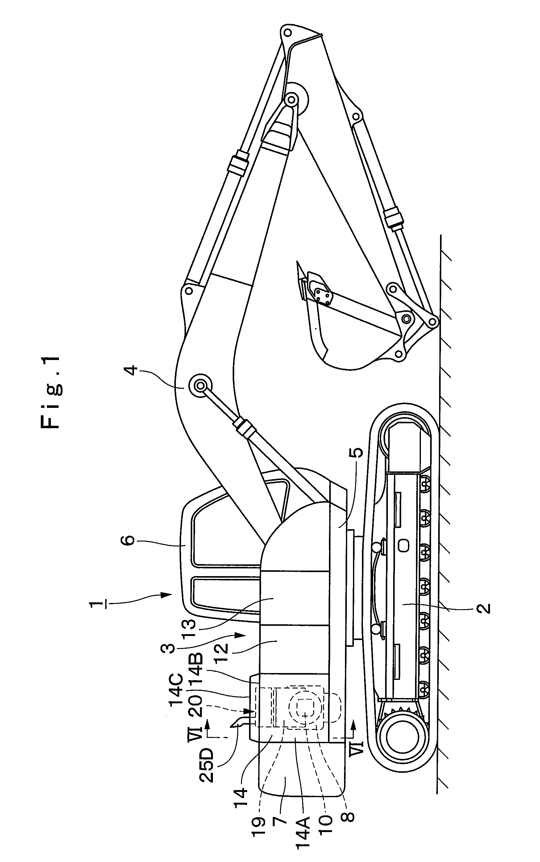
[0078]FIGS. 1 to 13 show the present invention. In FIG. 1, designated at 1 is a crawler type hydraulic excavator which is a typical example of construction machines, and the hydraulic excavator 1 is largely constituted by an automotive lower traveling structure 2, an upper revolving structure 3 which is swingably mounted on the lower traveling structure 2 and constitutes a vehicle body together with the lower traveling structure 2, and a working mechanism 4 liftably mounted on the front side of the upper revolving structure 3 to perform such as the operation of excavating earth and sand. Further, the lower traveling structure 2 and the upper revolving structure 3 are specific examples of the vehicle body in accordance with the invention.

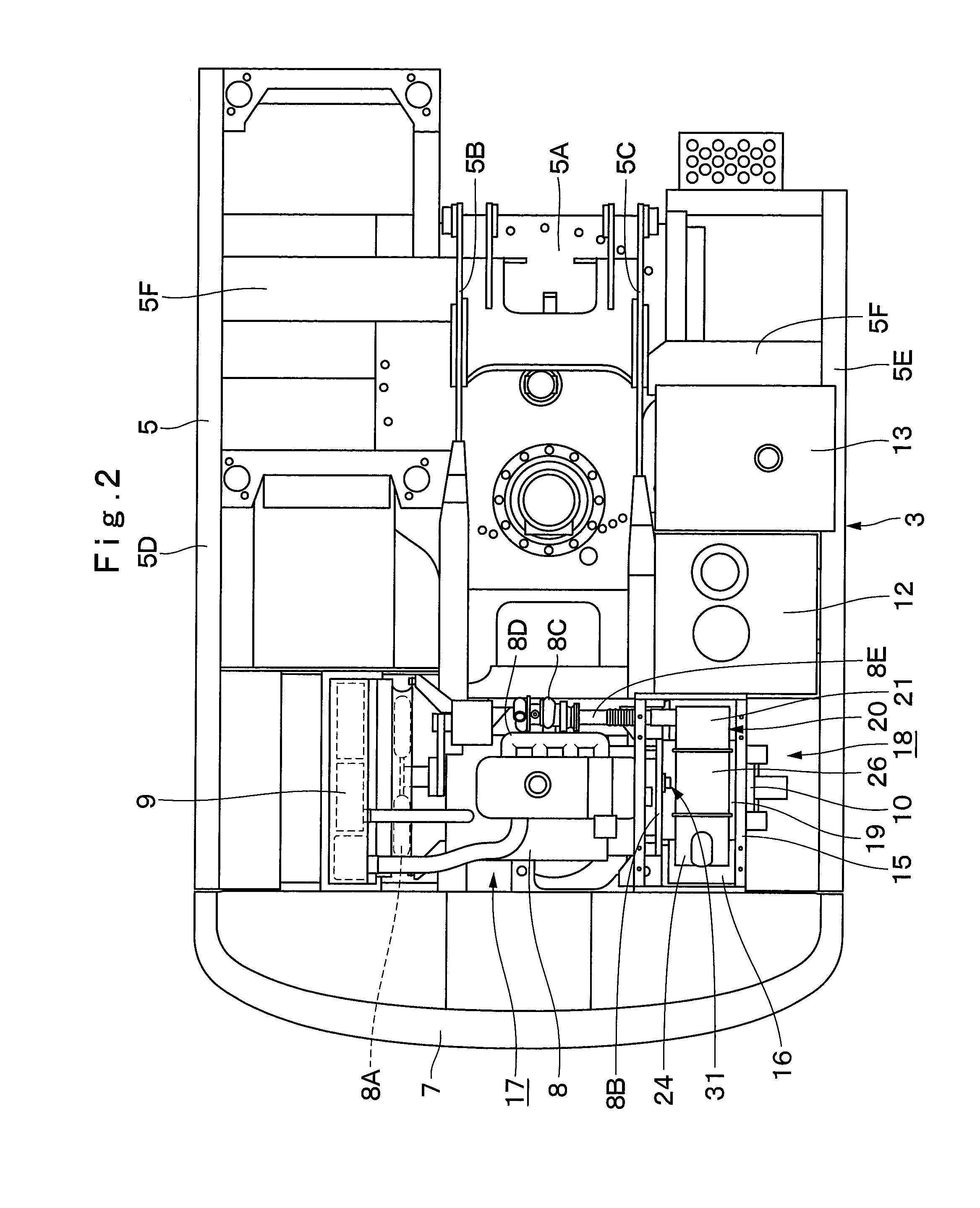
[0079]Here, with reference to FIGS. 1 to 7, a detailed description will be given of the upper revolving structure 3 for constituting the hydraulic excavator 1.

[0080]Indicated at 5 is a revolving frame of the upper revolving structure 3, and the revol...

third embodiment

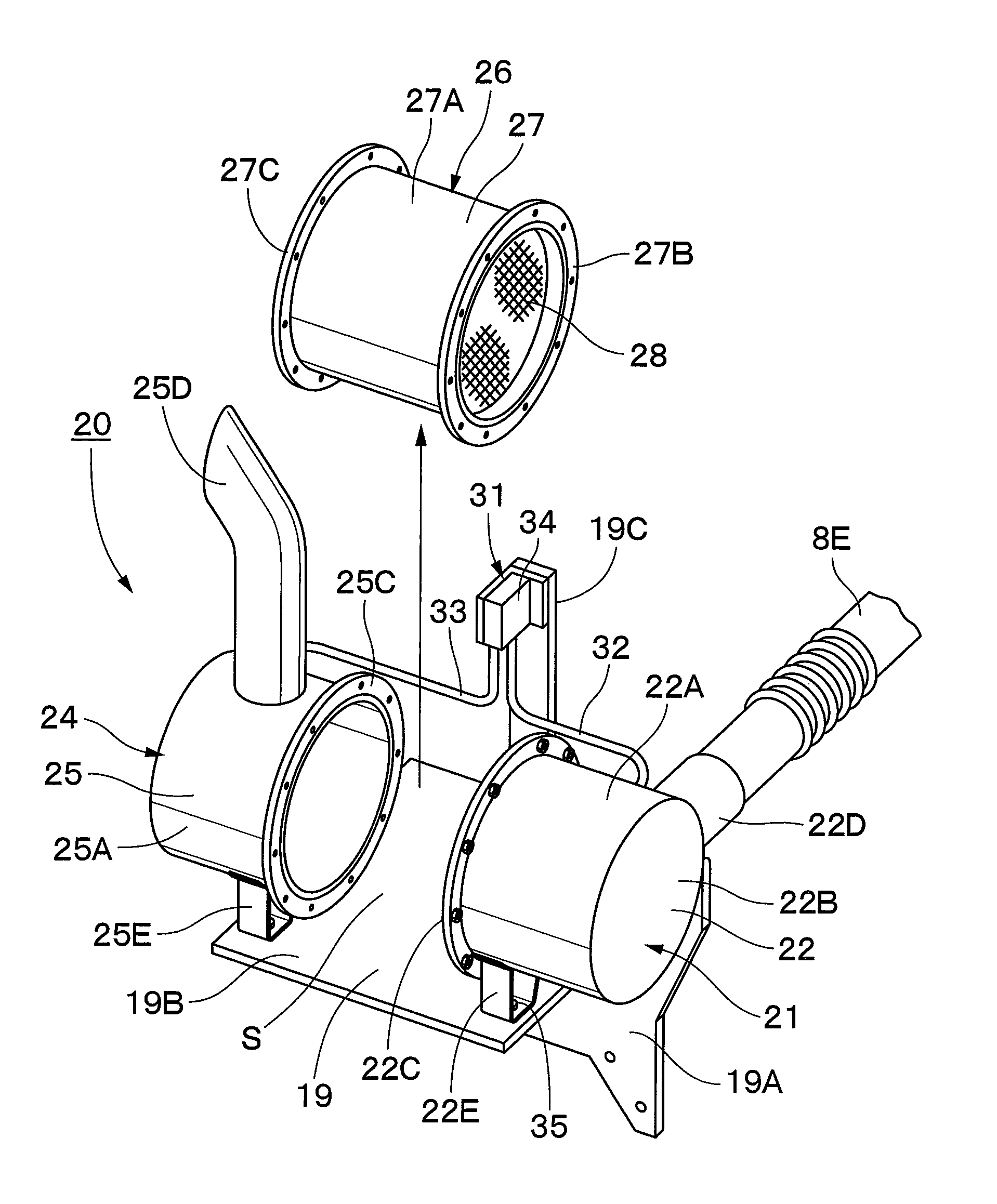
[0156]Designated at 53 is a pressure detection unit in accordance with the This pressure detection unit 53 is constituted by an upstream side pressure conduit 54, a downstream side pressure conduit 55, and the pressure sensor 56.

[0157]Indicated at 54 is the upstream side pressure conduit of the pressure detection unit 53, and the upstream side pressure conduit 54 is disposed along the outer periphery of the upstream cylinder 21, and one end thereof is connected to the pressure pick out portion 22F of the cylindrical case 22 of the upstream cylinder 21, while the other end thereof is connected to the below-described pressure sensor 56. In addition, denoted at 55 is the downstream side pressure conduit of the exhaust gas purifying device 51, and the exhaust gas purifying device 55 is disposed along the outer peripheries of the downstream cylinder 24 and the filter cylinder 26, and one end thereof is connected to the pressure pick out portion 25F of the cylindrical case 25 of the down...


PUM

PropertyMeasurementUnit
pressureaaaaaaaaaa
timeaaaaaaaaaa
temperatureaaaaaaaaaa

Abstract

An upstream cylinder (21) and a downstream cylinder (24) are fixedly mounted to a support member (19), and a filter cylinder (26) is provided mountably and dismountably between the cylinders (21) and (24). In consequence, only the filter cylinder (26) can be dismounted with the cylinders (21) and (24) left as they are on the support member (19), so that the maintenance operation of a particulate matter removing filter (28) can be performed easily. In addition, pressure conduits (32) and (33) and a pressure sensor (34) of a pressure detection unit (31) for detecting a clogged state of the particulate matter removing filter (28) are disposed at positions offset from a moving path (30) of the filter cylinder (26). In consequence, only the filter cylinder (26) can be easily mounted or dismounted without being obstructed by the pressure conduits (32) and (33) and the pressure sensor (34).

Description

TECHNICAL FIELD[0001]The present invention relates to a construction machine such as a hydraulic excavator, and more particularly to a construction machine equipped with an exhaust gas purifying device for purifying exhaust gas from an engine.BACKGROUND ART[0002]Generally, a hydraulic excavator as a typical example of construction machines is constituted by an automotive lower traveling structure, an upper revolving structure which is swingably mounted on the lower traveling structure, and a working mechanism liftably mounted on the front side of the upper revolving structure. An engine for driving a hydraulic pump is mounted on a rear portion of a revolving frame of the upper revolving structure, and an exhaust gas purifying device for purifying exhaust gas by removing harmful substances in the exhaust gas is provided in an exhaust pipe of the engine.[0003]Further, as an exhaust gas purifying device which is provided in a hydraulic excavator, a device is known which has a particula...

Claims


Application Information

Patent Timeline
Patent Type & Authority Applications(United States)
IPC IPC(8): F01N3/021
CPCB01D46/0002F01N2590/08B01D53/944B01D2257/404E02F9/00E02F9/0866E02F9/2025F01N3/0237F01N3/035F01N13/008F01N13/18F01N13/1894F01N2450/30F01N2470/18F01N2560/05B01D46/0086E02F9/2066E02F9/2095B01D53/94F01N3/02F01N3/28
Inventor EZAWA, MASANORIKAMIYA, SHOUHEIHIROSE, TAKASHIARAI, YASUSHI
Owner NIHON KENKI CO LTD
Why Eureka
Try Eureka