Ultrasonic inspection apparatus
a technology of ultrasonic and inspection apparatus, which is applied in the direction of analysing solids using ultrasonic/ultrasonic/infrasonic waves, instruments, and specific gravity measurements. it can solve the problems of difficult placement of objects to be inspected having complex shapes in predetermined positions with high reproducibility, requires an enormous amount of time and operation, and achieves high accuracy
- Summary
- Abstract
- Description
- Claims
- Application Information
AI Technical Summary
Benefits of technology
Problems solved by technology
Method used
Image

Examples
first embodiment
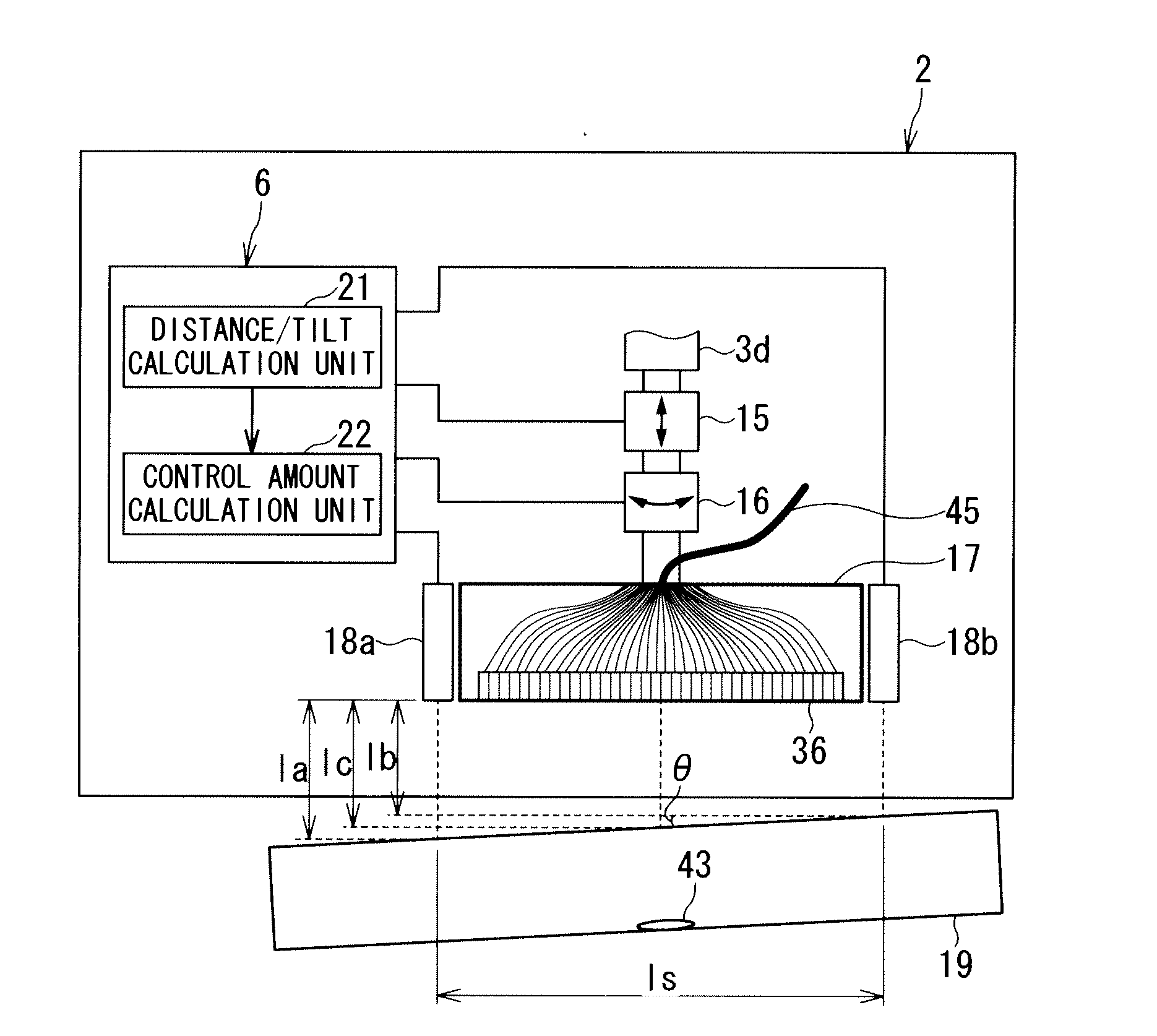
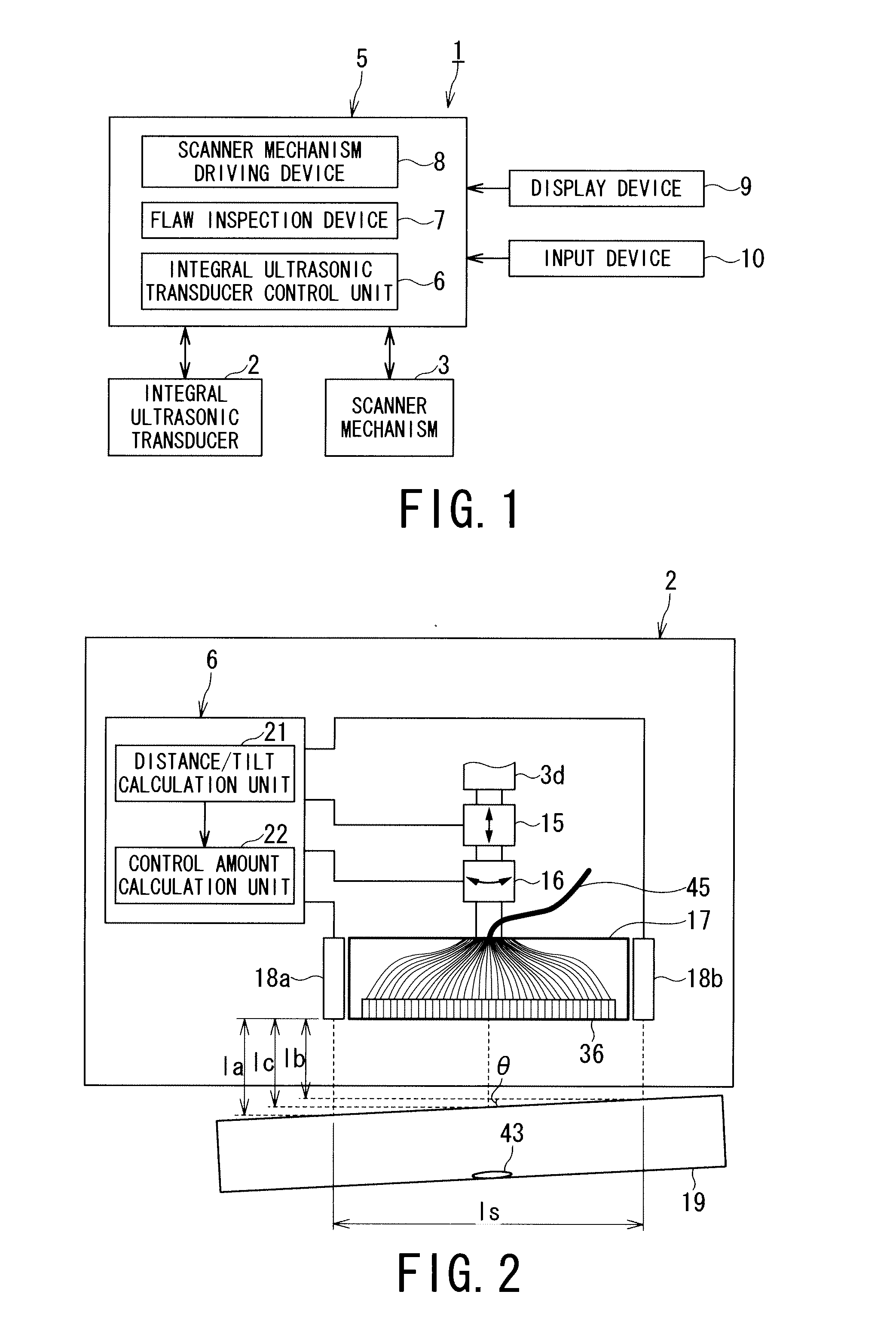
[0031]FIG. 1 is a schematic general configuration diagram showing an ultrasonic inspection apparatus 1 according to a first embodiment of the present invention.
[0032]The ultrasonic inspection apparatus 1 includes an actuator-integrated ultrasonic transducer (hereinafter referred to as an integral ultrasonic transducer) 2, a scanner mechanism 3, and an apparatus body 5 including an integral ultrasonic transducer control device 6, a flaw inspection device 7 and a scanner mechanism driving device 8.
[0033]The apparatus body 5 also includes a display device 9 that displays a two or three-dimensional flaw inspection image or the like obtained by an ultrasonic flaw inspection, and an input device 10 that receives inputs concerning various instructions. The display device 9 includes a display unit, a calculation unit, a storage unit, and the like, and can use a flat panel display such as a liquid crystal display, an LED (light emitting diode), an EL (electro luminescence), a VFD (vacuum flu...
second embodiment
[0099]An ultrasonic inspection apparatus according to a second embodiment of the present invention will be described hereunder.
[0100]FIG. 6 is a schematic configuration diagram of an integral ultrasonic transducer 2A and a flaw inspection device 7A of the ultrasonic inspection apparatus according to the second embodiment of the present invention.
[0101]The ultrasonic inspection apparatus of the second embodiment is different from the ultrasonic inspection apparatus 1 of the first embodiment in that a distance and a tilt between an opening surface of an ultrasonic transducer and an inspection region of an object to be inspected are calculated based on flaw inspection image information obtained by a flaw inspection device 7A. Configurations and components corresponding to those of the first embodiment are denoted by the same reference numerals, and overlapping descriptions will be omitted herein.
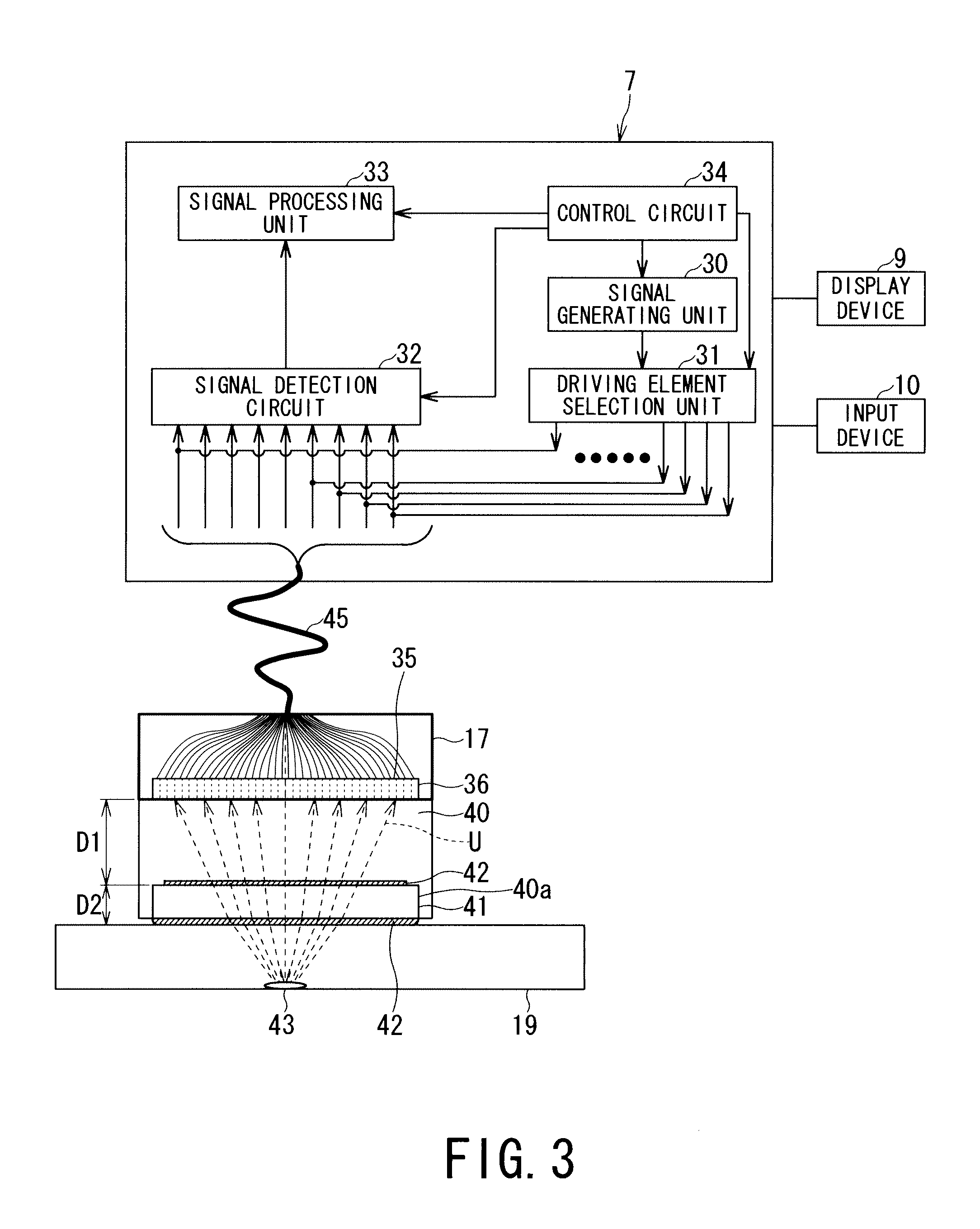
[0102]The flaw inspection device 7A connected to an ultrasonic transducer 17 includes a dis...
third embodiment
[0114]An ultrasonic inspection apparatus according to a third embodiment of the present invention will be described hereunder.
[0115]The ultrasonic inspection apparatus of the third embodiment is different from the ultrasonic inspection apparatus of the second embodiment in that an ultrasonic transducer 17B in an integral ultrasonic transducer 2B is provided on an arc, and the ultrasonic inspection apparatus is used for an ultrasonic flaw inspection of an inspection region of an object to be inspected 19B having inner and outer surfaces of a corner portion such as a pipe.
[0116]FIG. 8 is a schematic configuration diagram of the integral ultrasonic transducer 2B and the flaw inspection device 7B of the ultrasonic inspection apparatus according to the third embodiment of the present invention. Configurations and components corresponding to those in the first and second embodiments are denoted by the same reference numerals, and overlapping descriptions will be omitted herein.
[0117]The u...
PUM
 Abstract
Description
Claims
Application Information
 - R&D
- Intellectual Property
- Life Sciences
- Materials
- Tech Scout
- Unparalleled Data Quality
- Higher Quality Content
- 60% Fewer Hallucinations
Browse by: Latest US Patents, China's latest patents, Technical Efficacy Thesaurus, Application Domain, Technology Topic, Popular Technical Reports.
© 2025 PatSnap. All rights reserved.Legal|Privacy policy|Modern Slavery Act Transparency Statement|Sitemap|About US| Contact US: help@patsnap.com