Gas analyzer

a gas analyzer and gas detection technology, applied in the field of gas analyzers, can solve the problems of not being able to be obtained instantaneously, individuals exposed to smoke are at risk of being poisoned with hydrogen cyanide, etc., and achieve the effect of quick and simultaneous determination of carbon monoxide and hydrogen cyanide levels

Inactive Publication Date: 2011-01-06
FSP INSTR
View PDF30 Cites 12 Cited by
  • Summary
  • Abstract
  • Description
  • Claims
  • Application Information

AI Technical Summary

Benefits of technology

[0005]The subject invention is directed to a breath analyzer which is capable of detecting toxic gas levels from breath analysis. The subject invention includes a mouthpiece which is in communication with a plurality of discrete chambers, such as first and second discrete chambers, each being provided with a separate probe for breath analysis. The probes are connected to analyzers for determining detected levels of gas. In a first embodiment, a first probe may be provided for carbon monoxide detection with a second probe being provided for hydrogen cyanide detection. Advantageously, with this arrangement, breath analysis may be conducted on-site, for example at the site of a fire, to quickly and simultaneously determine carbon monoxide and hydrogen cyanide levels in a person's blood stream.
[0006]In a second embodiment, a first probe may be provided for detection of carbon monoxide and a second probe may be provided for detection of hydrogen. With this arrangement, a calibrated correction of measured carbon monoxide data can be made to correct for improperly detected hydrogen. As such, a highly accurate on-site measurement for carbon monoxide can be achieved.

Problems solved by technology

Such tests are typically done in a clinical or laboratory setting with results not being obtainable instantaneously.
Individuals exposed to smoke are at risk of being poisoned with hydrogen cyanide.

Method used


Image

  • Gas analyzer
  • Gas analyzer
  • Gas analyzer

Examples


Embodiment Construction

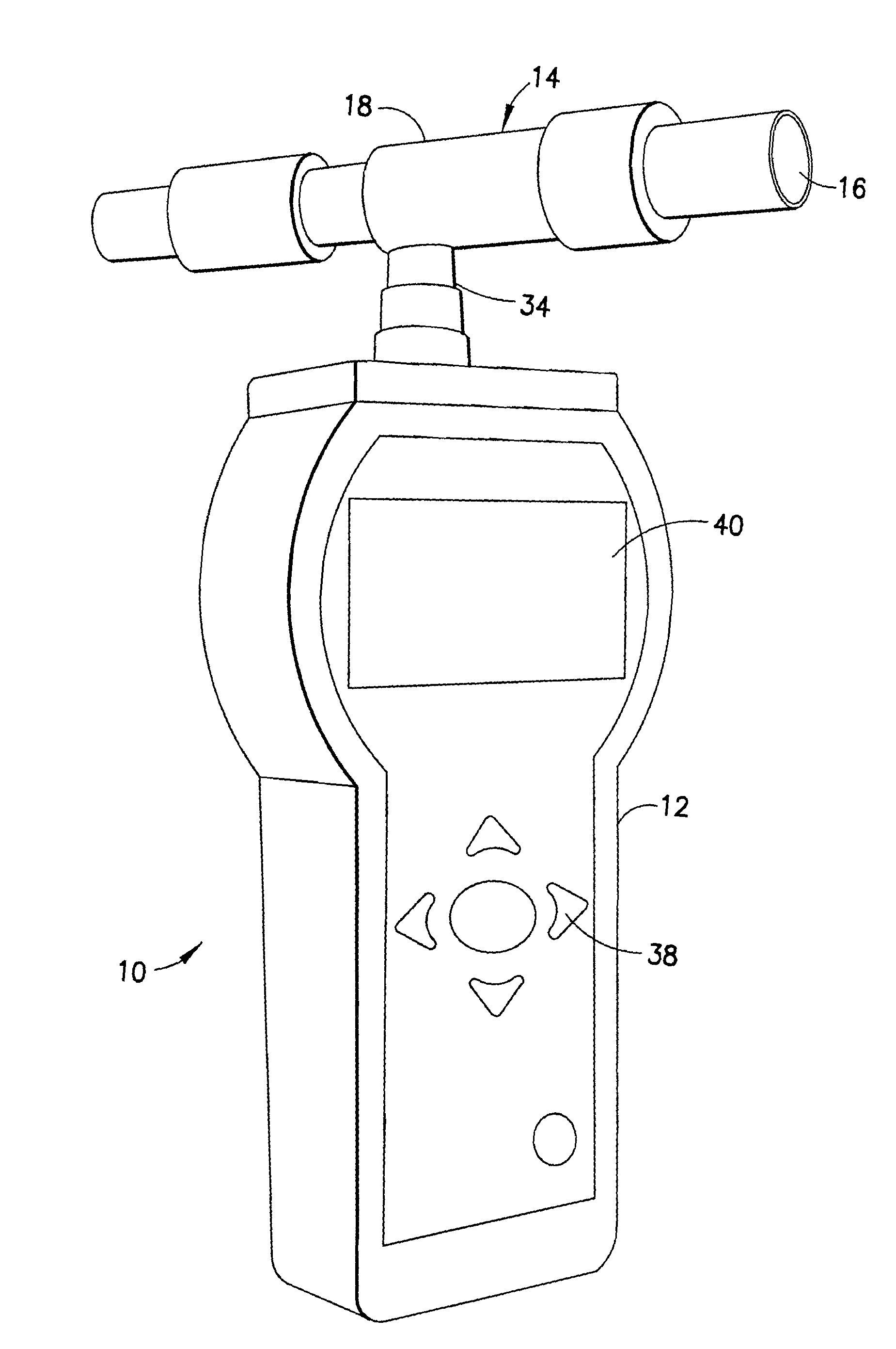
[0014]A breath analyzer 10 is provided herein which generally includes a housing 12 operatively coupled to a breath passage 14. The breath passage 14 includes a mouthpiece 16 which is open and formed to be comfortably accommodated by the mouth of a user. To use the breath analyzer 10, a user blows into the mouthpiece 16 of the breath passage 14. As shown in FIG. 1, the breath passage 14 may be a separate component from the housing 12 and be coupled thereto. Alternatively, the breath passage 14 may be disposed within the housing 12. It is preferred that the breath analyzer 10 be portable and be hand-held.

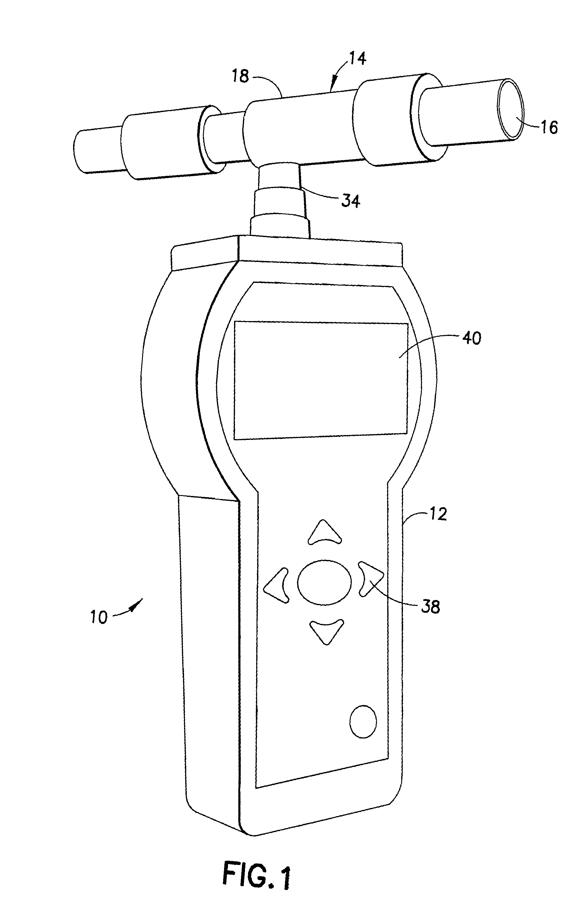
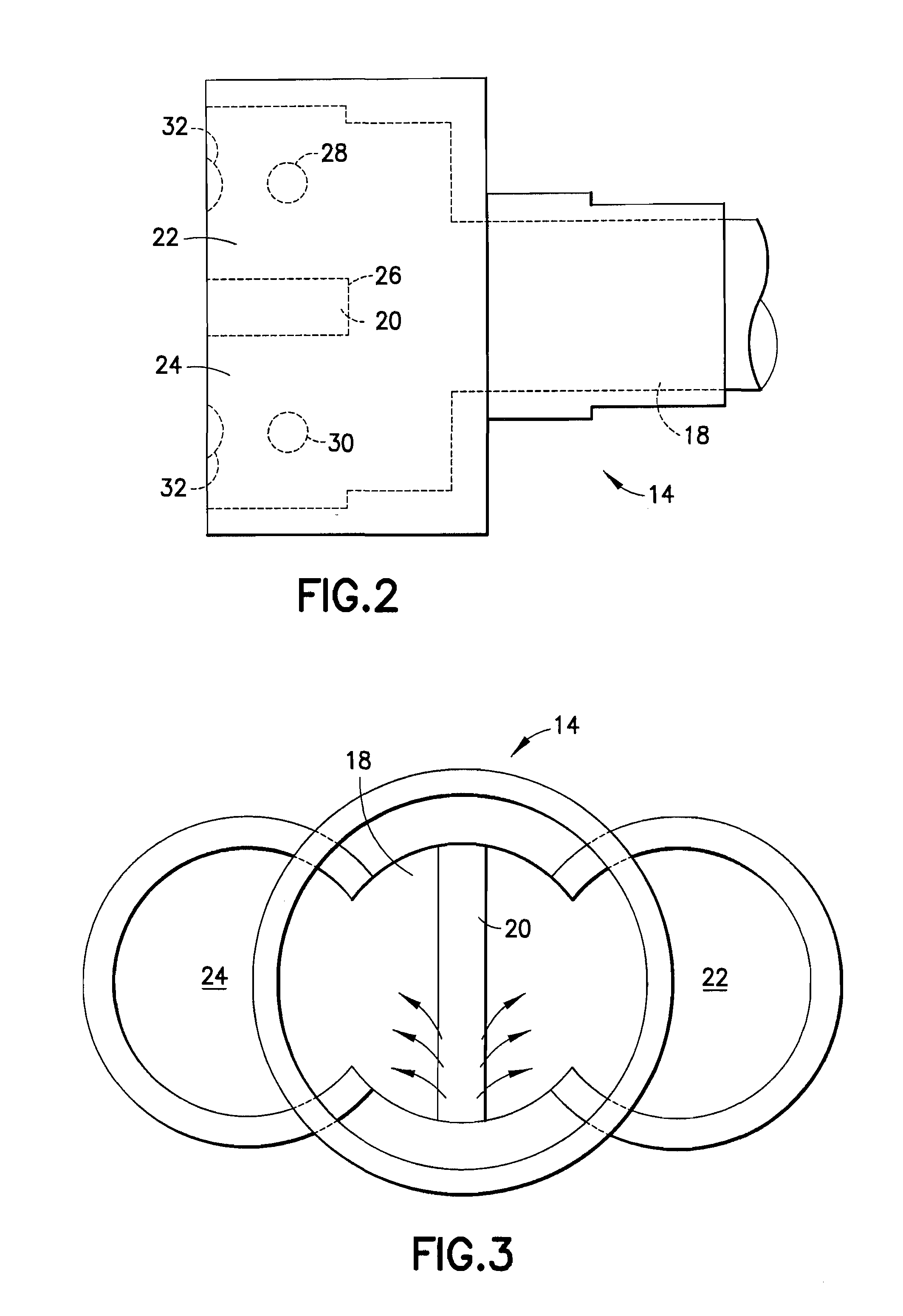
[0015]With reference to FIG. 2, the breath passage 14 includes a channel 18 that extends from the mouthpiece 16 and terminates at divider 20. The mouthpiece 16 may be a “drool-free” mouthpiece to minimize delivery of saliva into the channel 18. In addition, the mouthpiece 16 may be formed removable and replaceable for hygienic considerations. Single use of the mouthpiece 16 is prefer...


PUM

PropertyMeasurementUnit
timeaaaaaaaaaa
movementaaaaaaaaaa
electrochemicalaaaaaaaaaa

Abstract

The subject invention is directed to a breath analyzer which is capable of detecting toxic gas levels from breath analysis. The subject invention includes a mouthpiece which is in communication with a plurality of discrete chambers, such as first and second discrete chambers, each being provided with a separate probe for breath analysis. The probes are connected to analyzers for determining detected levels of gas. In a first embodiment, a first probe may be provided for carbon monoxide detection with a second probe being provided for hydrogen cyanide detection. Advantageously, with this arrangement, breath analysis may be conducted on-site, for example at the site of a fire, to quickly and simultaneously determine carbon monoxide and hydrogen cyanide levels in a person's blood stream. In a second embodiment, a first probe may be provided for detection of carbon monoxide and a second probe may be provided for detection of hydrogen. With this arrangement, a calibrated correction of measured carbon monoxide data can be made to correct for improperly detected hydrogen. As such, a highly accurate on-site measurement for carbon monoxide can be achieved.

Description

CROSS-REFERENCE TO RELATED APPLICATIONS[0001]This application is a continuation of U.S. application Ser. No. 12 / 301,254 filed Nov. 18, 2008, now pending, which is a National Stage Application of PCT Application No. PCT / US08 / 56387, filed Mar. 10, 2008, which claims priority of U.S. Provisional Patent Application No. 60 / 893,685, filed on Mar. 8, 2007, the entire contents of which are hereby incorporated by reference.BACKGROUND OF THE INVENTION[0002]Gas analyzers, particularly breath analyzers, are known in the prior art for detecting levels of toxins or other undesired substances in a person's body based on analysis of a person's expelled breath. A common form of breath analyzer is an alcohol breath analyzer which detects the level of alcohol in a person's blood stream based on measurements taken from the person's breath. Other forms of detectors are also known.[0003]Carbon monoxide (CO) poisoning is common amongst individuals exposed to smoke, particularly fire victims and firefighte...

Claims


Application Information

Patent Timeline
Patent Type & Authority Applications(United States)
IPC IPC(8): G08B17/10G01N33/497
CPCA61B5/097A61B5/411G01N33/497G01N2033/4975G01N33/004G01N33/0059G01N33/0031Y02A50/20
Inventor REILLY, JR., KEVIN JOHNSUTTORA, MARIO
Owner FSP INSTR
Why Eureka
Try Eureka