Leakage protective plug

a leakage protection and plug technology, applied in the direction of contact mechanisms, circuit-breaking switches, coupling device connections, etc., can solve the problems of poor protection of electric equipment and human safety, fire disaster, electric shock, etc., to avoid disasters, prevent disasters, and ensure the safety of electrical products

Inactive Publication Date: 2011-01-06
ZHANG KEQING +1
View PDF4 Cites 6 Cited by
  • Summary
  • Abstract
  • Description
  • Claims
  • Application Information

AI Technical Summary

Benefits of technology

[0013]The leakage protective plug in accordance with the present invention has the following advantages:
[0014]1. When an electrical product connected to the leakage protective plug of the present invention suffers from the faults of electric leakage or short circuit, the leakage protective plug of the present invention can automatically cut off the power source in time, preventing the occurrence of disasters while ensuring the safety of the electrical product.
[0015]2. When the leakage protective plug of the present invention is connected to the power source, the user can manually press down the test button, so that the test system in the leakage protective plug of the present invention will check if the whole electric circuit including the load circuit is in normal working state, avoiding the occurrence of disasters.

Problems solved by technology

In the existing electrical products, electric leakage or shot circuit fault caused by man-made or accident damage or material aging or external substances penetration might lead to electric shock, fire disaster and the like.
In addition, during the use of the plug, once the power is cut off but the plug is still connected with the socket, the plug will directly supply power to the electric equipment after the recovery of the power, which is not good for protection of electric equipments and human safety.

Method used


Image

  • Leakage protective plug
  • Leakage protective plug
  • Leakage protective plug

Examples


Embodiment Construction

[0020]The present invention will be clearer from the following description when viewed together with the accompanying drawings, which show, for purpose of illustrations only, the preferred embodiment in accordance with the present invention.

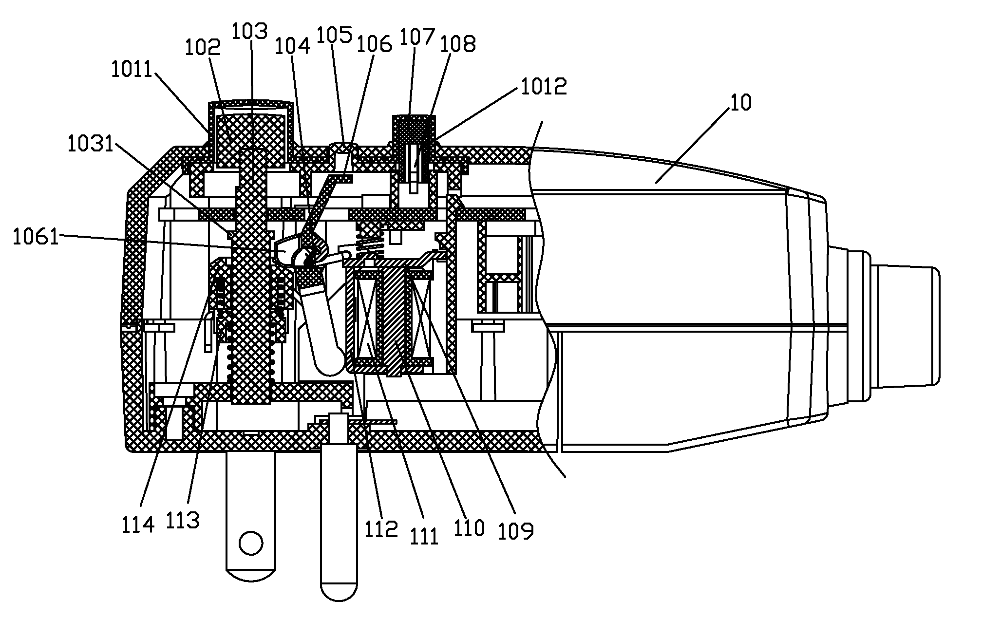
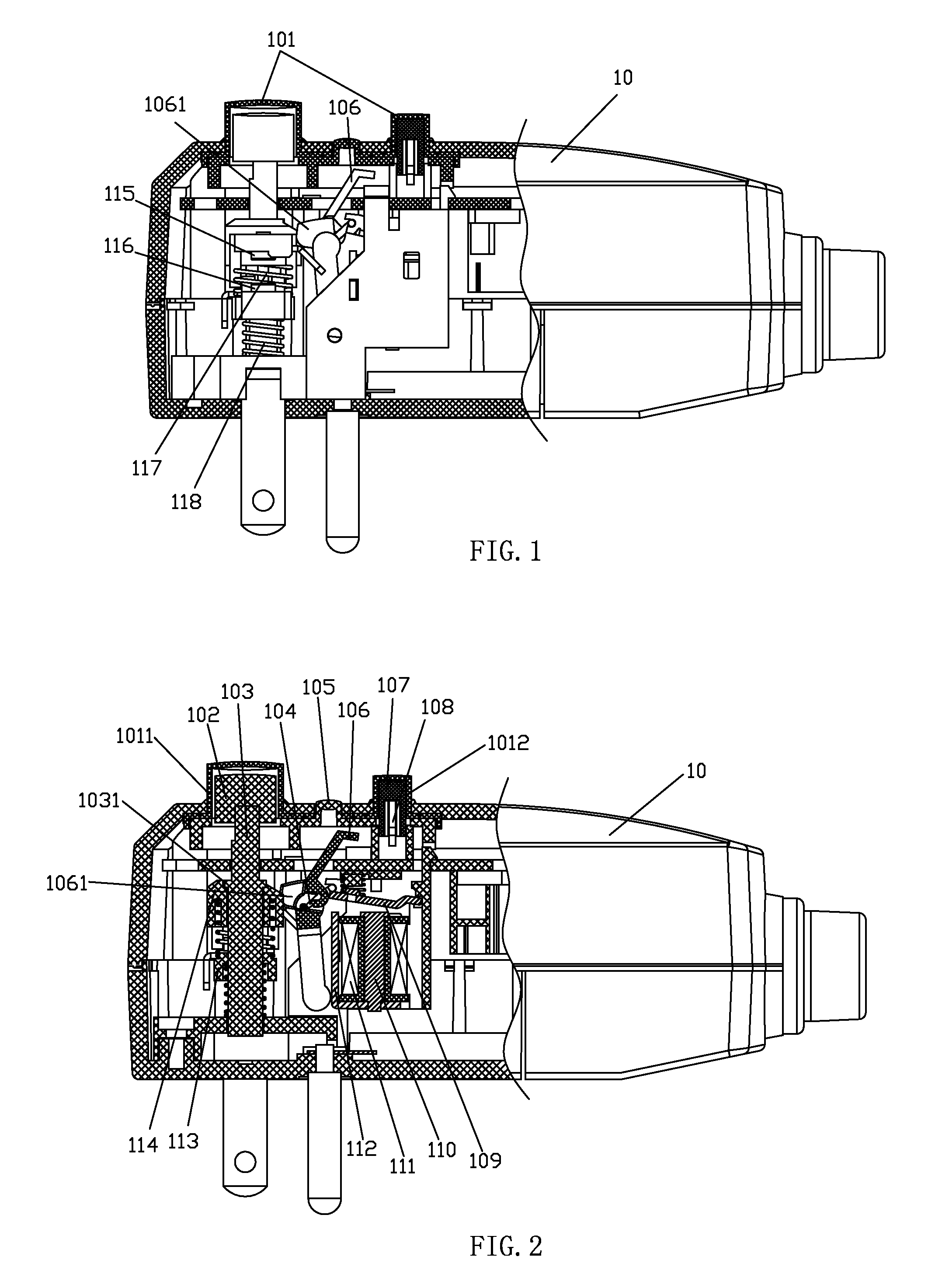
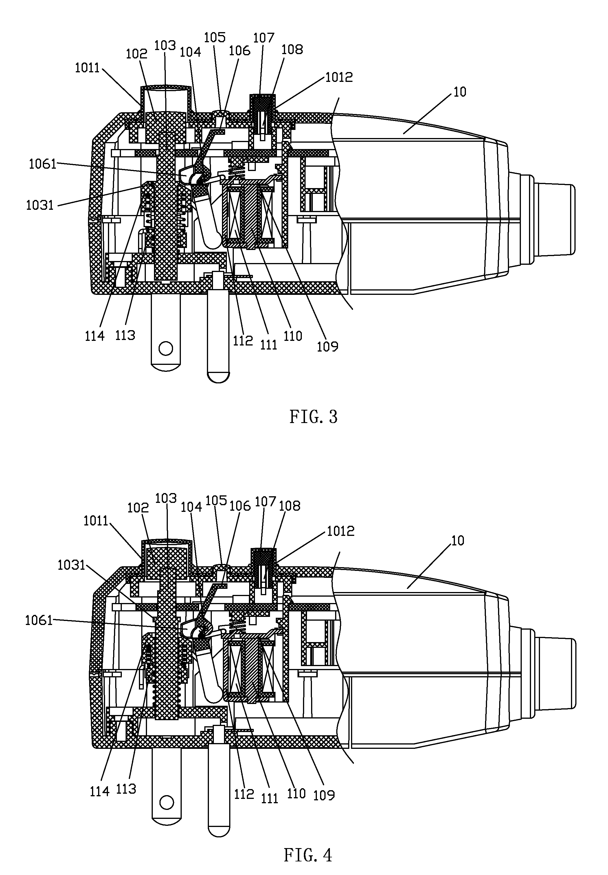
[0021]Referring to FIGS. 1-2, a leakage protective plug in accordance with the present invention comprises a case 10 and conductive electric contacts disposed in the case 10. On the top of the case 10 is fixed a protective cap 101. The protective cap 101 includes a reset button protective cap 1011 and a test button protective cap 1012. The reset button protective cap 1011 is interiorly provided with a reset button 102 connected with a push rod 103. The push rod 103 in order penetrates an electric contact upper panel 114, an upper spring 117, an electric contact lower panel 113 and a lower spring 118. The electric contact upper panel 114 is provided at a right side thereof with a locking member 106. The locking member 106 is linked with a brake co...


PUM


Abstract

A leakage protective plug comprises a case and electric contacts. A protective cap is fixed on the top of the case and includes a reset button protective cap and a test button protective cap. The reset button protective cap is interiorly provided with a reset button connected with a push rod which in order penetrates an electric contact upper panel, an upper spring, an electric contact lower panel and a lower spring. The electric contact upper panel is provided at a right side thereof with a locking member linked with a brake connecting rod which is linked with a brake plate. The brake plate is located at a lower right side of the locking member. Below the brake plate are disposed an electromagnet pole shoe, an electromagnet coil, and an electromagnet core. The test button protective cap is provided with a test button having a test electric contact.

Description

BACKGROUND OF THE INVENTION[0001]1. Field of the Invention[0002]The present invention relates to a leakage protective device; and more particularly to a leakage protective plug.[0003]2. Description of the Prior Art[0004]In the existing electrical products, electric leakage or shot circuit fault caused by man-made or accident damage or material aging or external substances penetration might lead to electric shock, fire disaster and the like. In addition, during the use of the plug, once the power is cut off but the plug is still connected with the socket, the plug will directly supply power to the electric equipment after the recovery of the power, which is not good for protection of electric equipments and human safety.[0005]The present invention has arisen to mitigate and / or obviate the afore-described disadvantages.SUMMARY OF THE INVENTION[0006]The primary objective of the present invention is to provide a safety and reliable leakage protective plug.[0007]To achieve the above obje...

Claims


Application Information

Patent Timeline
Patent Type & Authority Applications(United States)
IPC IPC(8): H02H3/00
CPCH01H83/04H01R2103/00H01R24/28H01R13/7135
Inventor ZHANG, KEQINGLI, JUNXIN
Owner ZHANG KEQING
Why Eureka
Try Eureka