Method of Implanting a Unicondylar Knee Prosthesis

a knee prosthesis and unicondylar technology, applied in the field of knee surgery, can solve the problems of damage to one or more bone surfaces and cartilage, severe pain, and eventually loss of movement, and achieve the effects of less invasiveness, more natural function, and improved knee joint function

Active Publication Date: 2011-01-06
BIOMET UK +2
View PDF12 Cites 15 Cited by
  • Summary
  • Abstract
  • Description
  • Claims
  • Application Information

AI Technical Summary

Benefits of technology

[0017]The present invention provides a partial knee replacement procedure that not only helps the knee joint function better but has also proven to improve both recovery and rehabilitation after surgery. The procedure involves removing only the diseased portion of the knee, traditional total knee replacement surgery involves removing or resurfacing more parts of the knee, including both condyles and often the underside of the kneecap.
[0018]The present invention is a less invasive approach to knee surgery and is particularly suited to patients who are still in the early stages of osteoarthritis. This means only the parts (the medial, ‘inner’ compartment or lateral ‘outer’ compartment) of the knee that have been damaged by the disease need replacing, therefore avoiding having to undergo a total knee replacement. This procedure preserves the healthy parts of the joint, as it only replaces one side of the knee, leading to an artificial joint with a function that is closer to the natural knees movements.
[0019]The component parts of the prosthesis have been designed to have surfaces that fit one another in all positions such that the kinematically complex movements of the knee are retained. This also means that component parts of the prosthesis wear out very slowly. A further benefit of this procedure is that by retaining all the undamaged parts, in particular the cruciates and ligaments, the joint bends better and has a more natural function.

Problems solved by technology

Arthritis causes damage to one or more of the bone surfaces and cartilage where the bones rub together.
This friction can cause severe pain and eventually loss of movement.
In some cases, there may be significant damage on only one side of the joint or to only one of the condyles.

Method used


Image

  • Method of Implanting a Unicondylar Knee Prosthesis
  • Method of Implanting a Unicondylar Knee Prosthesis
  • Method of Implanting a Unicondylar Knee Prosthesis

Examples


Embodiment Construction

[0039]The present invention will be discussed hereinafter in detail in terms of various embodiments of a method of implanting a unicondylar knee prosthesis. In the following description, numerous specific details are set forth in order to provide a thorough understanding of the present invention. It will be obvious, however, to those skilled in the art that the present invention may be practiced without these specific details.

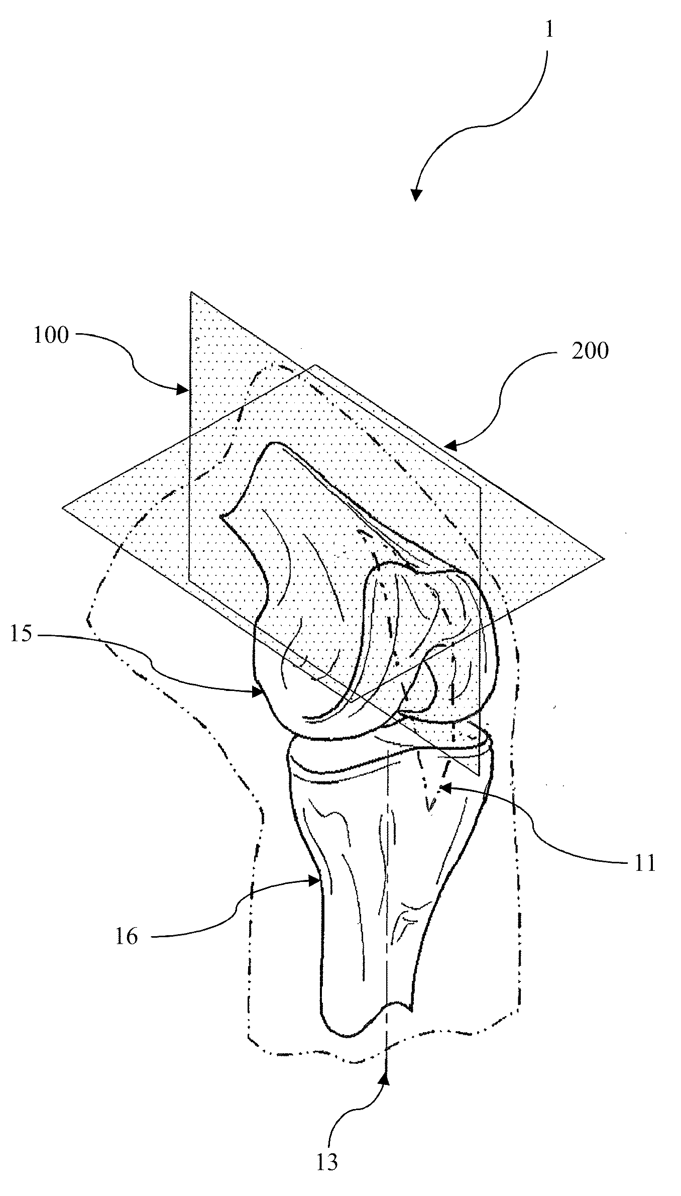
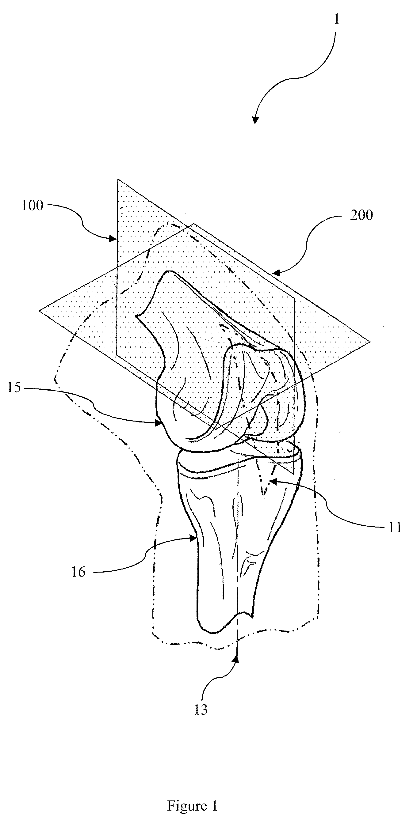
[0040]With reference to FIG. 1, it will be appreciated that the anterior-posterior plane 100 and the medial-lateral plane 200 are not exactly and specifically located on the body but can provide general guidance as to orientation and location. As such, alignment of the prosthetic 20 (FIG. 3) to the anterior-posterior plane 100 and the spigot (not shown) of the femoral component 30 and the femur 15 to the medial-lateral plane 200 can provide a general orientation of the femoral component 30 relative to the femur 15 and the tibia 16. Also shown in FIG. 1 is the l...


PUM


Abstract

A method of implanting a lateral unicondylar knee prosthesis in a lateral articulating portion of a femur having a lateral condyle for engagement with a tibia, the method including the steps of: bending a patients knee such that the knee is not in full extension; making an incision through the skin, muscle, and other soft tissue until the damaged bone surfaces are exposed; resecting an end portion of the lateral tibia; resecting an end portion of the lateral femoral condyle; attaching a tibial prosthetic component to the resected end portion of the tibia; attaching a lateral femoral condyle prosthetic component to the resected end portion of the lateral femoral condyle; determining the thickness of a mobile bearing member with the knee in full extension; and inserting the mobile bearing member between the tibial prosthetic component and the femoral prosthetic component.

Description

FIELD OF THE INVENTION[0001]The present invention relates to a method for knee surgery, and in particular, to a method of implanting a unicondylar knee prosthesis.BACKGROUND OF THE INVENTION[0002]The knee joint is where the end of the upper leg bone (femur) meets the top of the lower leg bone (tibia). The end of the femur consists of two condyles, which are like runners or wheels on each side of the bone that both roll and slide with respect to the other surface. These condyles are located on top of the tibia, which is like a platform that is slightly dished on the medial side but slightly convex on the lateral side. Thus, on each side of the joint, there is an area of contact between the two bones. When the knee is bent, the condyles of the femur roll and slide on top of the tibia at these two areas of contact. A third bone, the kneecap (patella), glides over the front and end of the femur.[0003]The two condyles form two articular bodies of the femur and are respectively named its ...

Claims


Application Information

Patent Timeline
Patent Type & Authority Applications(United States)
IPC IPC(8): A61F2/38A61B17/58
CPCA61B17/1764A61F2/30965A61F2/38A61F2/3868A61F2/461A61F2/4684A61F2310/00179A61F2240/001A61F2310/00017A61F2310/00023A61F2310/00029A61F2310/00095A61F2002/3895A61B17/155A61B17/157
Inventor MURRAY, DAVIDDODD, CHRIS
Owner BIOMET UK
Why Eureka
Try Eureka