Engine block coating system
- Summary
- Abstract
- Description
- Claims
- Application Information
AI Technical Summary
Benefits of technology
Problems solved by technology
Method used
Image
Examples
second embodiment
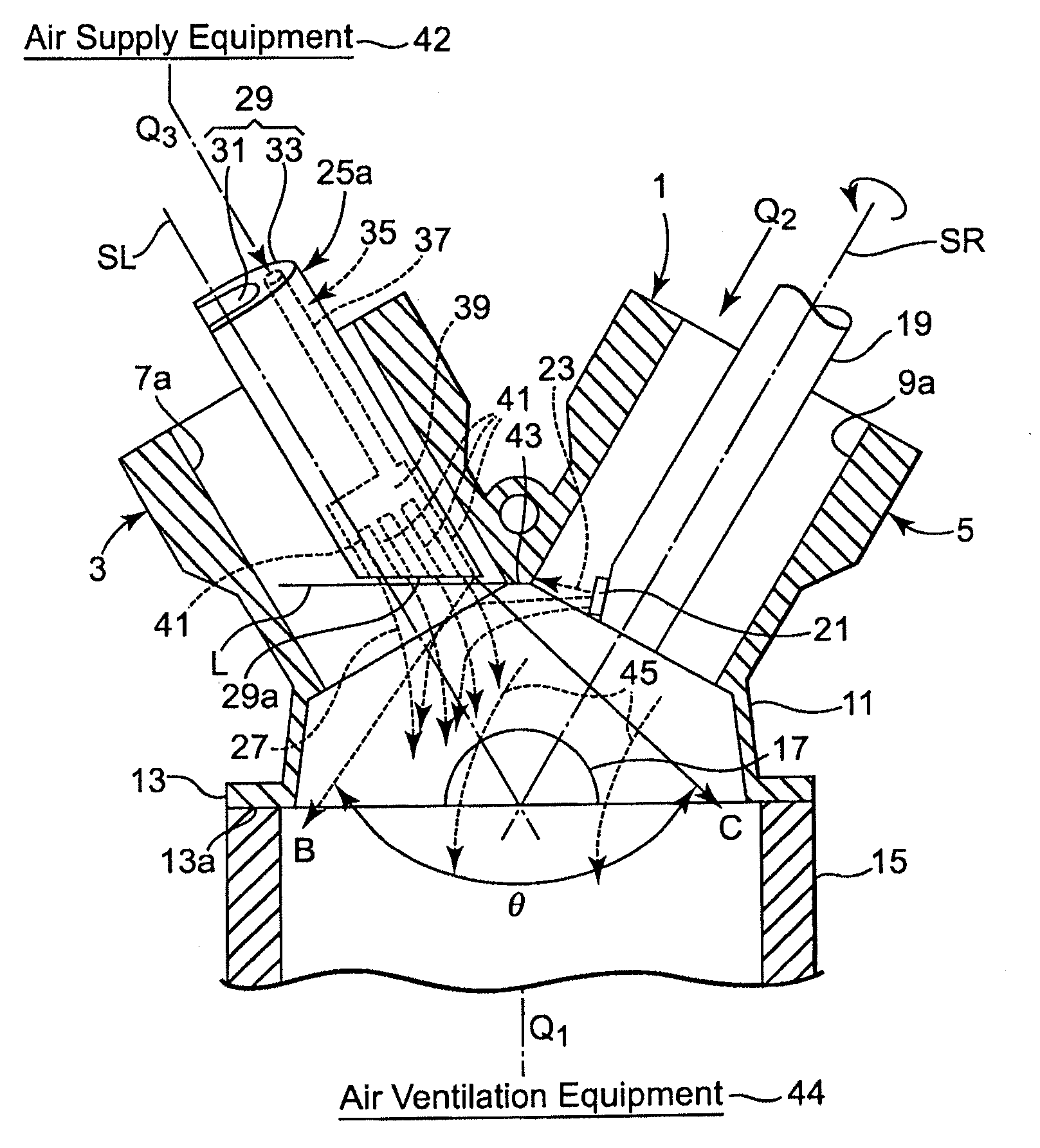
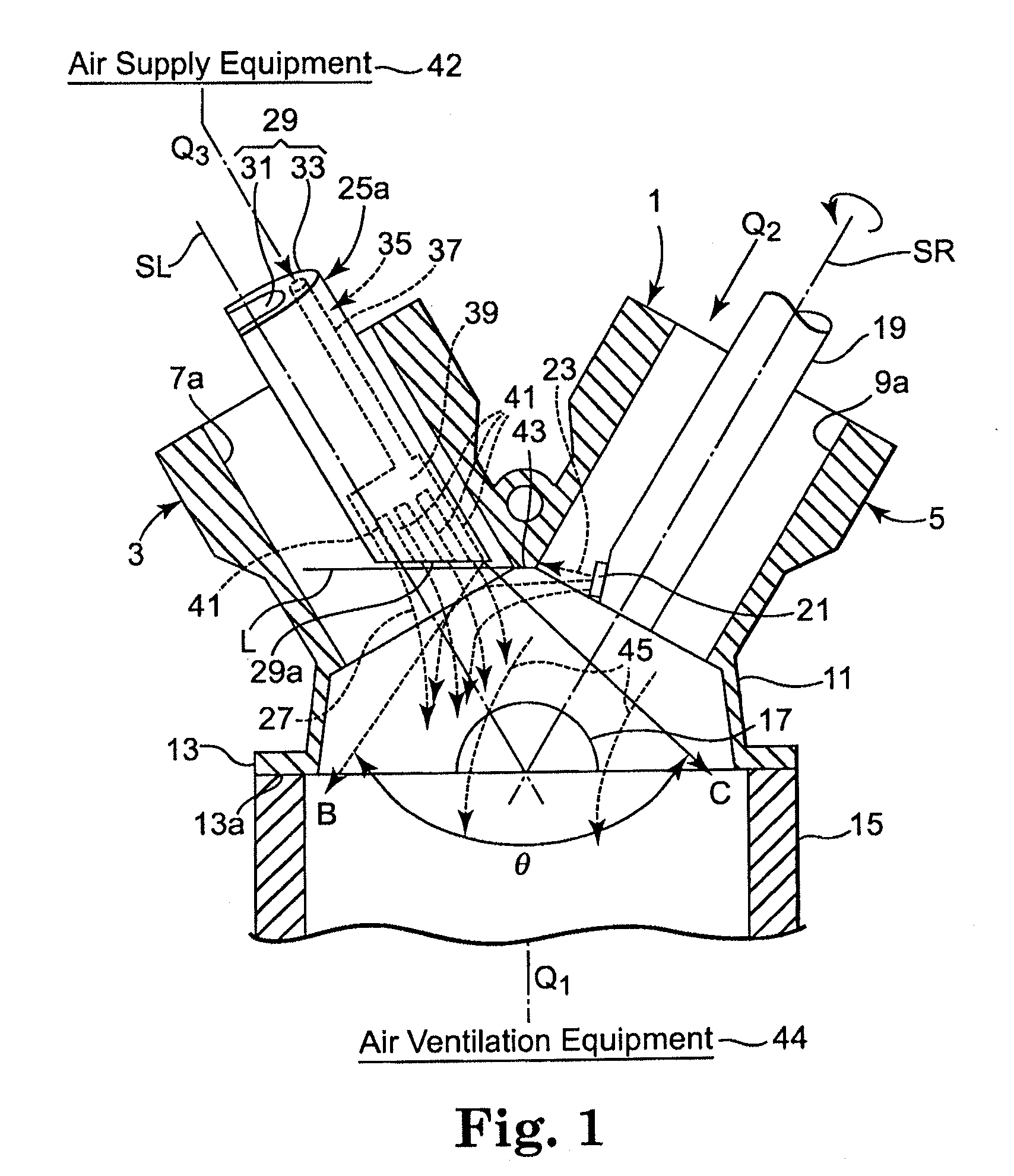
[0049]FIG. 3 is a cross-sectional view corresponding to FIG. 1 showing coating masking techniques in the second exemplary embodiment of the invention. In this embodiment a gas gun 250 is used instead of the gas guns 25a, 25b and 25c described in FIG. 1. Except for structure related to the gas gun 250, the structure and notations for members are the same as that in FIG. 1.
[0050]The gas gun 250 in the second exemplary embodiment has a gun housing 290 as a housing having a hollow rectangular shape. Inside the housing, the gas nozzle 350 is provided on the gas path 370 located on the side of rear anchor. The gas path 370 includes an expansion space 390 prior to outlets 410. Multiple outlets 410 on the side of rear anchor communicate with the expansion space 390.
[0051]As in the first exemplary embodiment, the direction of the gas spray of each outlet 410 on the gas nozzle 350 is inside the opening on the opposite side of the cylinder bore in the crankcase 11. The flow of the discharging ...
third embodiment
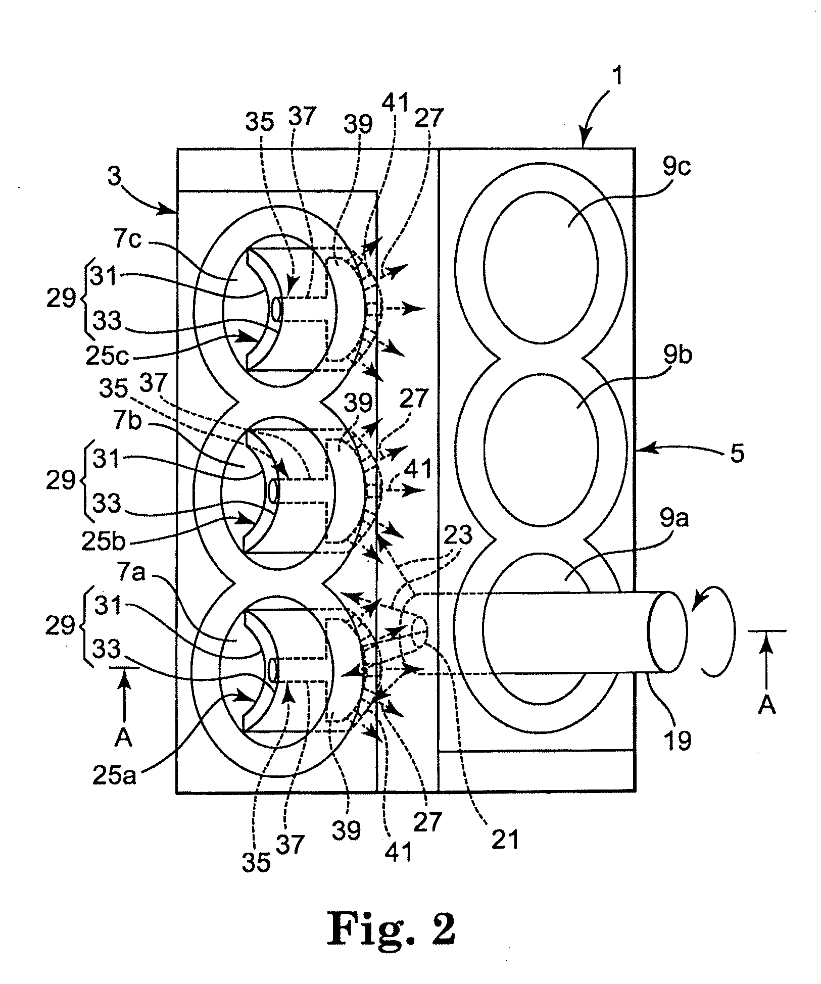
[0056]FIG. 4 is a cross-sectional view corresponding to the FIG. 1, showing the coating masking method of the third exemplary embodiment. FIG. 5 is a cross-sectional view of D-D in FIG. 4. In FIG. 4 and FIG. 5, the same symbols are allocated to the same part or corresponding part of each component in FIG. 1 and FIG. 2. Also FIG. 4 and FIG. 5 show an example of forming a coating on the cylinder bore 9b, wherein the gas gun 25b is inserted into the cylinder bore 7b opposing the cylinder bore 9b.
[0057]The gas gun 25b in this embodiment has basically the same structure as that shown in FIG. 1. As shown in FIG. 5, it also includes the crank journal wall oriented nozzles 51 and 53 that are directed to the crank journal walls 47 and 49 situated in the upper and the lower parts in FIG. 5 respectively. Furthermore the third exemplary embodiment includes the cylinder bore oriented nozzle 55 directed to the cylinder bore 9b. The crank journal walls 47 and 49 comprise the crank journal 17 that...
fourth embodiment
[0073]FIG. 6 is a cross-sectional view, showing the coating masking method of the engine block in the fourth exemplary embodiment of the invention. In FIG. 6, the same symbols are allocated to the same part or corresponding part of each component in FIG. 1.
[0074]The gas gun 25a in this embodiment has basically the same structure as that shown in FIG. 1; however, the supply source that supplies gas to the gas gun 25a is cooling gas supply equipment 77 instead of the gas supply equipment 42 in FIG. 1, and the entire gas gun 25a or a portion thereof is insulated to reduce or prevent condensation.
[0075]As compared to previously described embodiments, the cooling gas supplied from the cooling gas supply equipment 77 further decreases the adhesion of a coating material 23 to the cylinder bore 7a, the crank journal walls 47 and 49, and the inner surface 11a of the crankcase 11.
[0076]Since the degree of adhesion of a coating decreases at low temperature, a coating adhering in this condition...
PUM
| Property | Measurement | Unit |
|---|---|---|
| Adhesion strength | aaaaa | aaaaa |
Abstract
Description
Claims
Application Information
 - R&D
- Intellectual Property
- Life Sciences
- Materials
- Tech Scout
- Unparalleled Data Quality
- Higher Quality Content
- 60% Fewer Hallucinations
Browse by: Latest US Patents, China's latest patents, Technical Efficacy Thesaurus, Application Domain, Technology Topic, Popular Technical Reports.
© 2025 PatSnap. All rights reserved.Legal|Privacy policy|Modern Slavery Act Transparency Statement|Sitemap|About US| Contact US: help@patsnap.com


