
Vehicular air conditioning apparatus

a technology of air conditioning apparatus and cooling chamber, which is applied in the direction of heat exchange apparatus, vehicle heating/cooling devices, vehicle components, etc., can solve the problems of noise generation, narrow ventilation passages inside the cooling means, and lowered cooling efficiency of the cooling means, so as to prevent the freezing of the heat exchanger

Inactive Publication Date: 2011-01-13
KEIHIN CORP +1
View PDF15 Cites 23 Cited by
  • Summary
  • Abstract
  • Description
  • Claims
  • Application Information

AI Technical Summary

Benefits of technology

[0009]A general object of the present invention is to provide a vehicular air conditioning apparatus, which is capable of preventing freezing of a heat exchanger due to water droplets becoming frozen and adhering to surfaces of the heat exchanger.
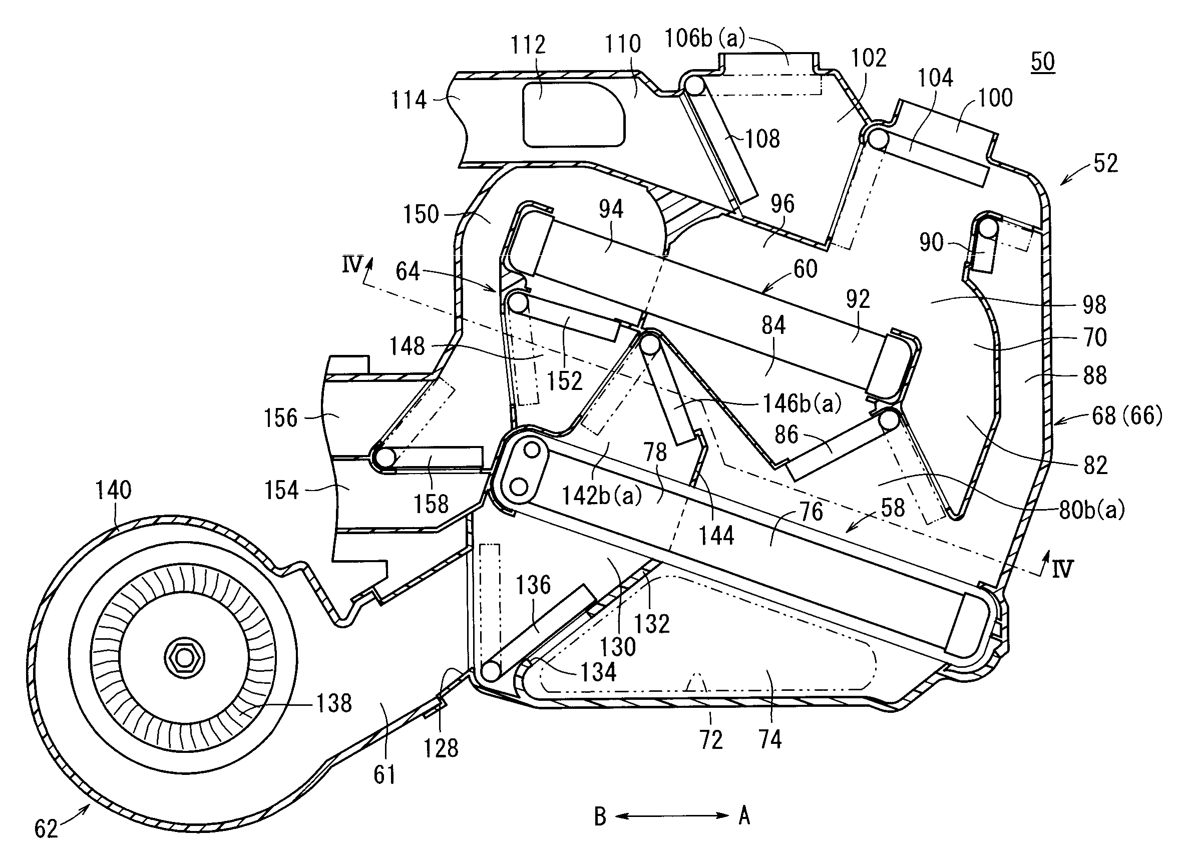
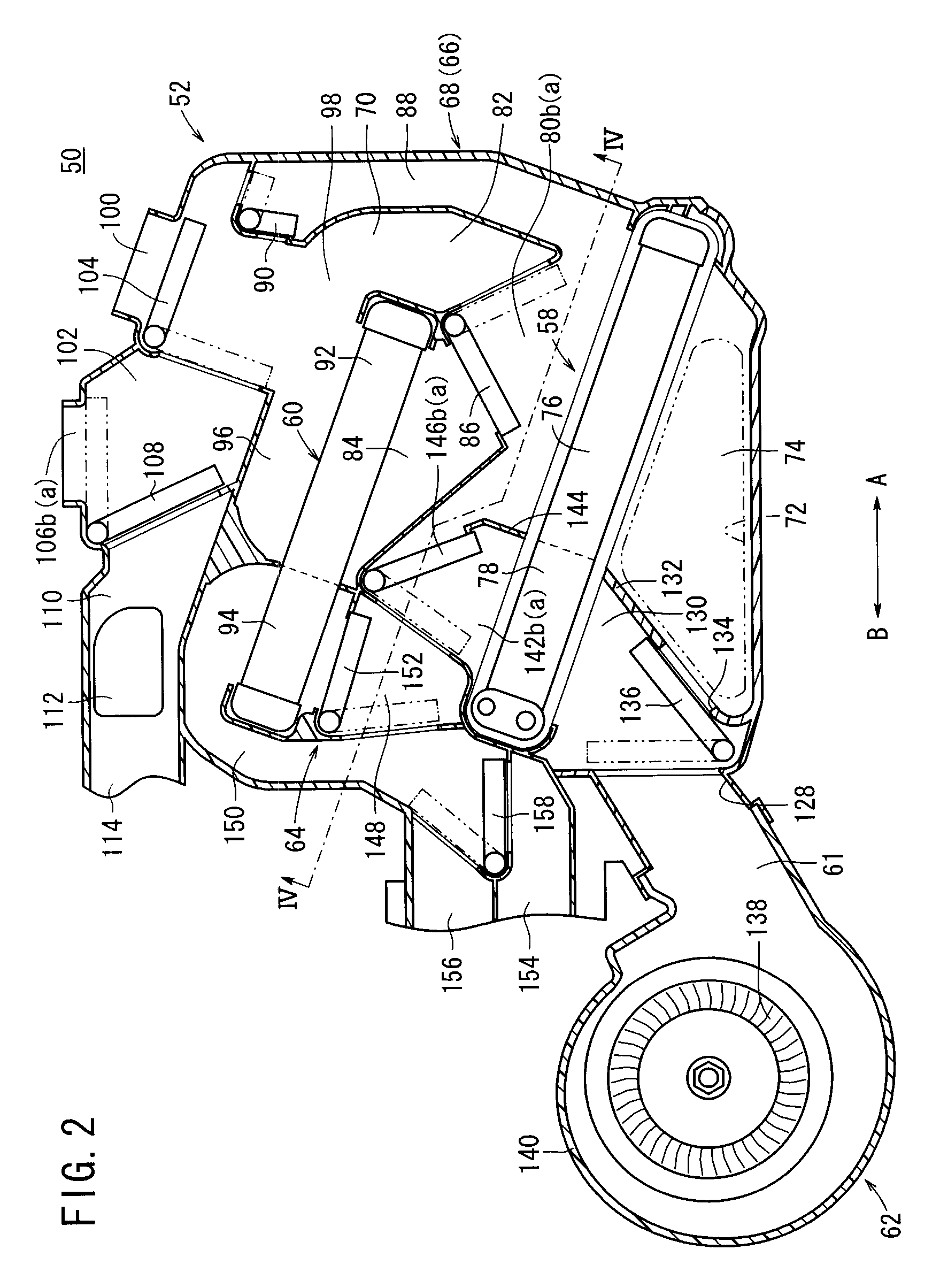
[0011]With the present invention, the switching damper is disposed upstream from the heat exchanger and between the first passage connected to the first blower and the second passage connected to the second blower, such that the switching damper is capable of switching a communication state between the first passage and the second passage. Accordingly, by driving the switching damper corresponding to the driving states of the first blower and the second blower, and freely switching the communication state between the first passage and the second passage, a portion of the air that is supplied to the first passage from the first blower can be made to flow to the side of the second passage.
[0012]As a result, by supplying air from the first blower, which is supplied to the first passage, to the side of the second passage by means of the switching damper, the air can be made to flow also with respect to a location of the heat exchanger facing the second passage. Therefore, for example, when air is not supplied from the second blower, by driving the switching damper and supplying air, which is supplied from the first blower, into the heat exchanger, freezing of water droplets that adhere to the surface of the heat exchanger and freezing within the heat exchanger can reliably be prevented.

Problems solved by technology

In this case, at a duct connected to the first blower (hereinafter also referred to as a passage), as a result of the air rate therein becoming small or completely non-existent, carrying out of heat exchange in a cooling means disposed within such a passage becomes problematic, so that the cooling means is subjected to freezing, and more specifically, water droplets on the surface of the evaporator making up the cooling means become frozen and adhere thereto, and as a result, a disadvantage results in that ventilation passages inside the cooling means are narrowed and the cooling efficiency of the cooling means is lowered.
Further, in the case that driving of the first blower is halted while blowing of air is carried out only by the second blower, a portion of the air that is blown from the second blower passes through the heater core and the evaporator, resulting in a disadvantage, in that noise is generated due to such air flowing to the side of the first blower.
Furthermore, a sense of discomfort is imparted to passengers in the vehicle due to back-flowing of air into the vehicle compartment from the first blower.

Method used


Image

  • Vehicular air conditioning apparatus
  • Vehicular air conditioning apparatus
  • Vehicular air conditioning apparatus

Examples


Embodiment Construction

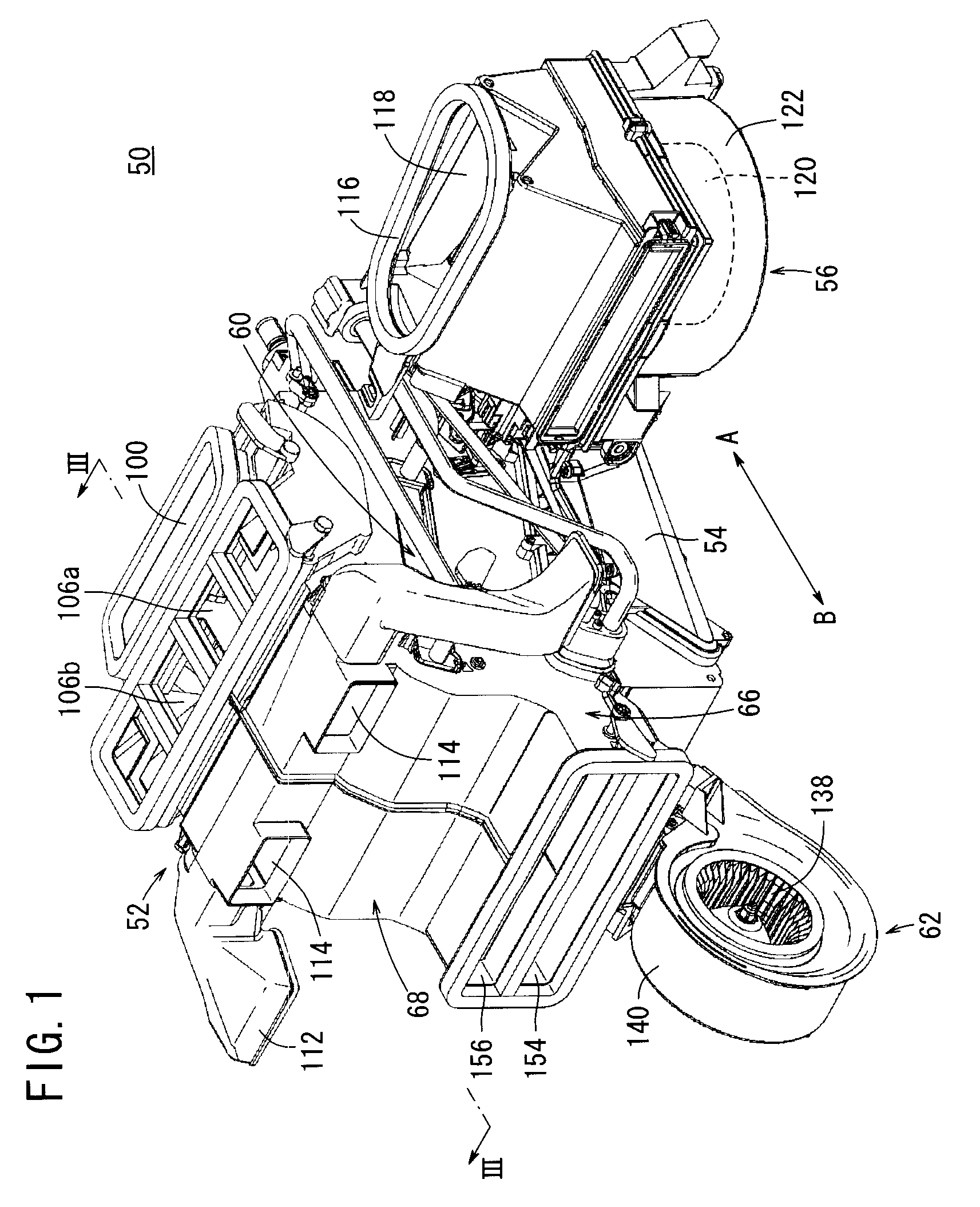
[0024]A preferred embodiment of a vehicular air conditioning apparatus shall be presented and explained in detail below with reference to the accompanying drawings. In FIG. 1, reference numeral 50 indicates a vehicular air conditioning apparatus according to an embodiment of the present invention. The vehicular air conditioning apparatus 50, for example, is installed in a vehicle having three rows of seats arranged along the direction of travel of the vehicle. In the following descriptions, the first row of seats in the vehicle compartment of the vehicle is designated as front seats, the second row of seats is designated as middle seats, and the third row of seats is designated as rear seats.

[0025]Further, the vehicular air conditioning apparatus 50 is installed so that the righthand side thereof shown in FIG. 2 (in the direction of arrow A) is oriented toward the front side of the vehicle, whereas the lefthand side (in the direction of arrow B) is oriented toward the rear side of t...


PUM


Abstract

In a vehicular air conditioning apparatus, a first blower unit is connected by a connection duct to a side portion of a casing constituted by respective air passages. On a lower portion of the casing, the first blower unit is connected together with a second blower unit. As a result of a controller controlling driving of an ventilation switching damper, based on a load voltage to a second blower fan of the second blower unit, a first front passage and a first rear passage are placed in communication, whereby a portion of the air from the first blower unit passes through the first front passage, a communication opening, and the first rear passage, and is supplied to a second cooling section of an evaporator, such that when the second blower fan is rotated at a low speed, freezing of water droplets in the second cooling section is avoided.

Description

BACKGROUND OF THE INVENTION[0001]1. Field of the Invention[0002]The present invention relates to a vehicular air conditioning apparatus mounted in a vehicle for blowing air into a vehicle compartment that has been adjusted in temperature by a heat exchanger, for thereby performing temperature adjustment of the vehicle compartment.[0003]2. Description of the Related Art[0004]In a vehicular air conditioning apparatus that is mounted in a vehicle, internal and external air is drawn into a casing by a blower, and after cooled air, which has been cooled by an evaporator that forms a cooling means, and heated air, which has been heated by a heater core that forms a heating means, are mixed together in the casing at a predetermined mixing ratio, the mixed air is blown out from a defroster blow-out port, a face blow-out port, or a foot blow-out port, whereby adjustment of temperature and humidity in the vehicle compartment is carried out.[0005]With this type of vehicular air conditioning ap...

Claims


Application Information

Patent Timeline
Patent Type & Authority Applications(United States)
IPC IPC(8): B60H1/00
CPCB60H1/00064B60H1/00828B60H2001/002B60H2001/00135B60H2001/00164B60H2001/00099
Inventor NANAUMI, KYOSUKEIMASAWA, MITSUFUMIKITAMURA, TSUNETOSHIKANEMARU, JUNICHIKAKIZAKI, SHINJI
Owner KEIHIN CORP
Learn More