
Modular mobile robot

a robot and module technology, applied in the field of modules, can solve the problems of difficult removal of the arm assembly from the robot chassis, difficult repair and replacement of the tracks, motors and other components, and often unclear structure of the robot chassis, etc., and achieve the effect of easy decoupling and easy decoupling

Active Publication Date: 2011-01-13
FOSTER-MILLER
View PDF40 Cites 48 Cited by
  • Summary
  • Abstract
  • Description
  • Claims
  • Application Information

AI Technical Summary

Benefits of technology

[0011]It is a further object of this invention to provide such a robot which includes, in one embodiment, fairly wide, fairly closely spaced tracks to reduce high centering and for maneuverability in close confines.
[0013]It is a further object of this invention to provide such a robot which, in one embodiment, includes track modules which are self contained and easily decoupled from and coupled to the robot chassis.
[0014]It is a further object of this invention to provide such a robot which includes, in one embodiment, a turret which is also self contained and easily decoupled from and coupled to the robot chassis.
[0017]It is a further object of this invention to provide such a robot which includes, in one embodiment, a novel track tensioning mechanism which allows the tracks to be quickly removed and replaced.

Problems solved by technology

In general, the robot chassis (or frame or body) is often ill-defined.
Components of the tracks cooperate with components of the robot chassis in a way that makes repair and replacement of the tracks, motors, and other components difficult.
In the assignee's “Talon” robot, for example, the arm assembly is not easily removable from the robot chassis.
Therefore, it is typically not possible to easily remove the turret from such robots.
A turret designed for one robot chassis cannot typically be used with another robot chassis.
Wider, more closely spaced tracks prevent the high centering problem but limit access to the chassis and the components and subsystem housed thereby, notably the batteries providing power for the robot drive and other subsystems.

Method used


Image

  • Modular mobile robot
  • Modular mobile robot
  • Modular mobile robot

Examples


Embodiment Construction

[0049]Aside from the preferred embodiment or embodiments disclosed below, this invention is capable of other embodiments and of being practiced or being carried out in various ways. Thus, it is to be understood that the invention is not limited in its application to the details of construction and the arrangements of components set forth in the following description or illustrated in the drawings. If only one embodiment is described herein, the claims hereof are not to be limited to that embodiment. Moreover, the claims hereof are not to be read restrictively unless there is clear and convincing evidence manifesting a certain exclusion, restriction, or disclaimer.

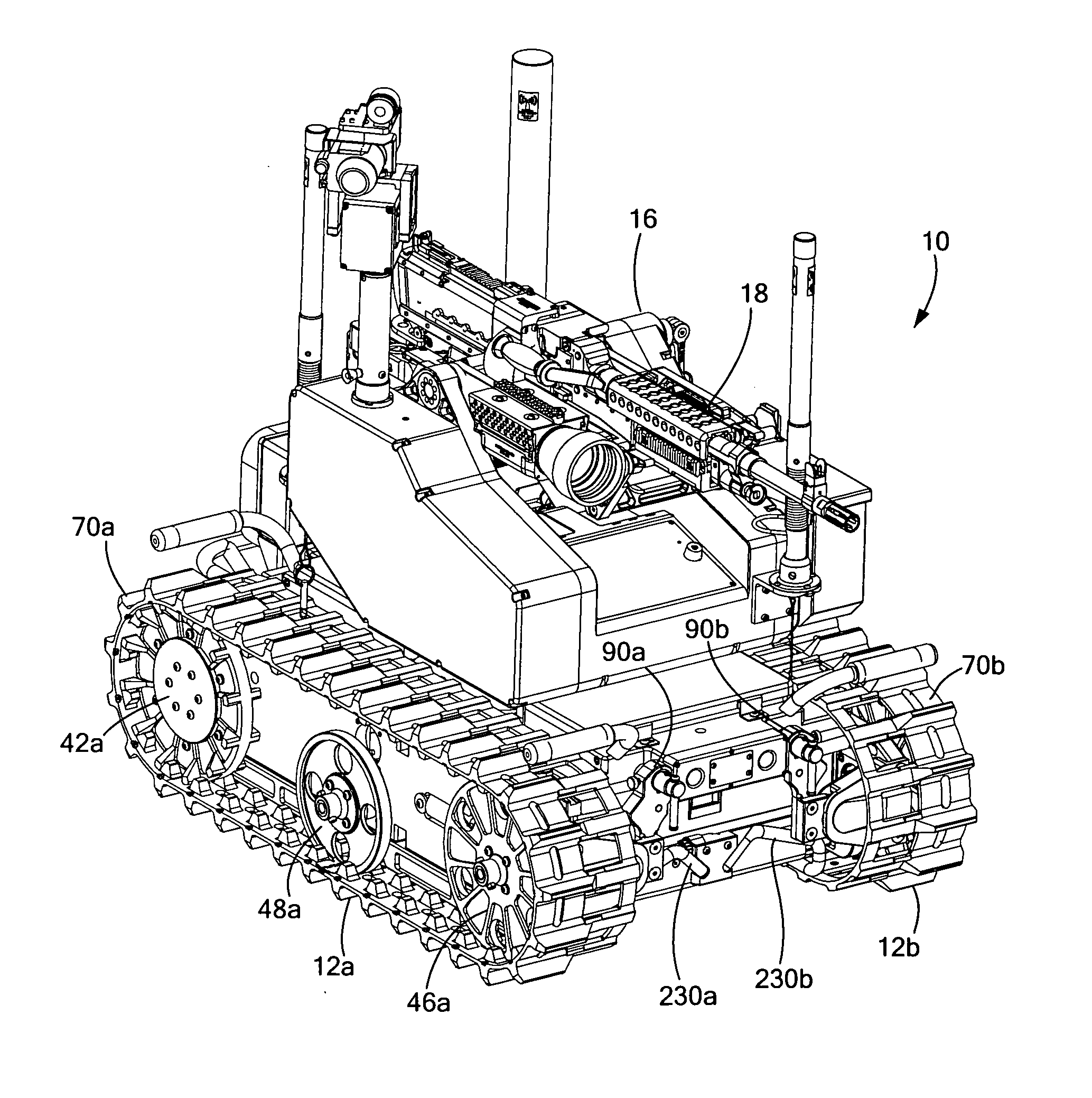
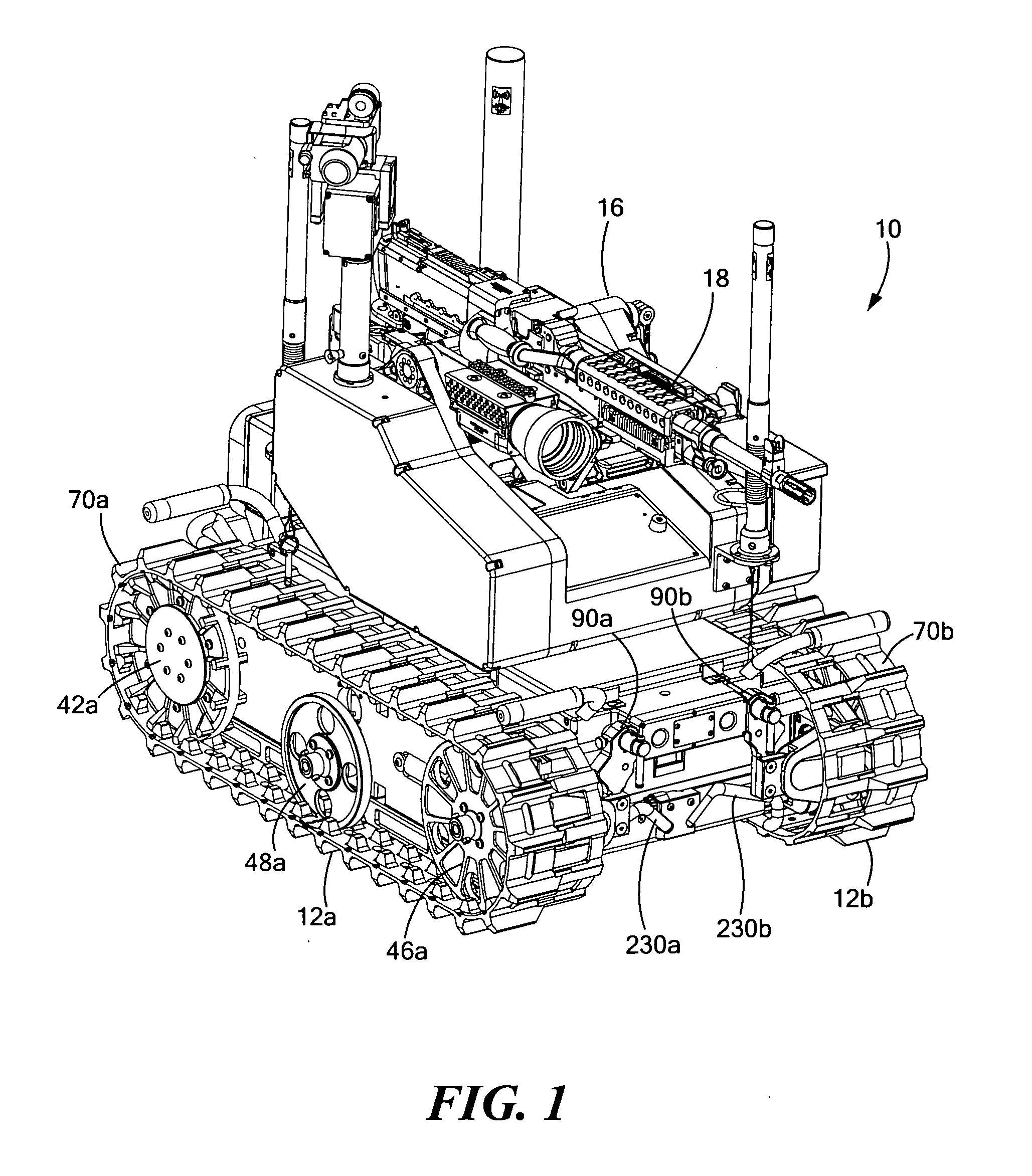
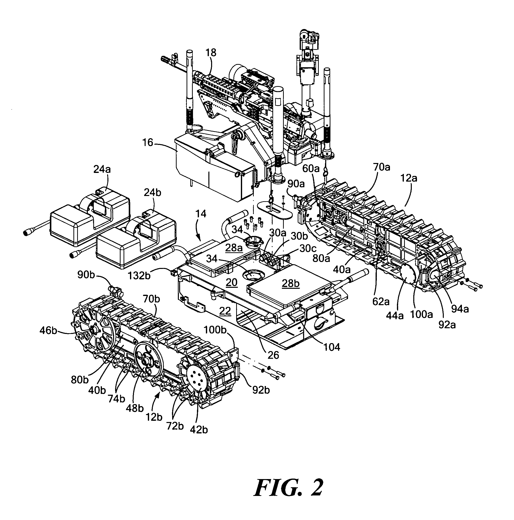
[0050]FIG. 1 shows an example of modular mobile robot 10 in accordance with the subject invention. Preferably, right hand and left hand track modules 12a and 12b are similarly configured and are removeably coupled to robot chassis 14, FIG. 2. The preferred track modules are fully self-contained (e.g., the only required elec...


PUM


Abstract

A modular mobile robot with a chassis including a power source housed therein. Right and left hand track modules are each removeably coupled to the robot chassis. Each track module includes a side plate, at least one drive wheel rotatable with respect to the side plate, a motor for driving the drive wheel, at least one idler rotatable with respect to the side plate, and a track extending around the drive wheel, the side plate, and the idler. A turret assembly with its own turret drive subsystem is removeably coupled to the robot chassis via a quick release mechanism.

Description

RELATED APPLICATIONS[0001]This application hereby claims the benefit of and priority to U.S. Provisional Application Ser. No. 61 / 007,681, filed on Dec. 14, 2007 under 35 U.S.C. §§119, 120, 363, 365, and 37 C.F.R. §1.55 and §1.78.FIELD OF THE INVENTION[0002]The subject invention relates to modular robots, typically remotely controlled mobile robots.BACKGROUND OF THE INVENTION[0003]Remotely controlled mobile robots are useful in a variety of applications and include military, police, fire, SWAT, and other users. Some robots have articulatable arms; others are equipped with weapons. Many have sensors, cameras, and the like. Some robots have wheels while others have tracks. In general, the robot chassis (or frame or body) is often ill-defined.[0004]For example, U.S. Pat. No. 6,431,296 discloses a robotic platform with a main body including three tubes rigidly connecting the track side plates. The motors, drive pulleys, chains, and other mechanisms for driving the tracks are typically ho...

Claims


Application Information

Patent Timeline
IPC IPC(8): B62D55/00B25J5/00
CPCB60L2200/40G05B2219/40304B62D55/104B62D55/13B62D55/135B62D55/14B62D55/15B62D55/244B62D55/305B62D63/025F41A23/34F41H7/005F41H7/02F41H11/16B62D55/084
Inventor ANDRUS, LANCE L.DESTEFANO, BRIANALBIN, SCOTT R.
Owner FOSTER-MILLER
Learn More