Mounting Structure for NOx Reduction Device for Construction Machine

a technology of nox reduction and mounting structure, which is applied in the direction of machines/engines, mechanical equipment, transportation and packaging, etc., can solve the problems of oil flowing through the hydraulic hose coming into contact, the maintenance of the hydraulic pump is rendered difficult, etc., and achieves excellent ease of maintenance, excellent versatility, and facilitates the maintenance of the hydraulic pump.

Active Publication Date: 2011-01-13
NIHON KENKI CO LTD
View PDF51 Cites 46 Cited by
  • Summary
  • Abstract
  • Description
  • Claims
  • Application Information

AI Technical Summary

Benefits of technology

[0020]In the present invention, the counterweight is provided with the recessed section formed therein, the reduction catalyst is arranged in the recessed section, and the PM collection filter is arranged in the engine compartment. It is, therefore, only the PM collection filter out of the PM collection filter and reduction catalyst that is arranged around the hydraulic pump disposed in the engine compartment. As a consequence, the surrounding space of the hydraulic pump can be assured to remain wide open, so that the maintenance of the hydraulic pump is facilitated. Therefore, excellent ease of maintenance is assured for the hydraulic pump.
[0021]The reduction catalyst as a heat source and the hydraulic hose connected to the hydraulic pump can be isolated from each other. As a consequence, even if the hydraulic hose bursts and the oil in the hydraulic hose leaks out, it is possible to prevent a fire by the leaked oil, thereby making it possible to assure excellent safety.
[0022]In the engine compartment, it is necessary to arrange only the PM collection filter out of the PM collection filter and reduction catalyst. Therefore, the mounting structure according to the present invention can be applied even to a construction machine the width of which is small, and can be assured to have excellent versatility.

Problems solved by technology

However, a problem such as that to be described below arises if an attempt is made to apply the conventional technology disclosed in Patent Document 1 to a construction machine such as a hydraulic excavator as shown in FIGS. 5 and 6.
As the reduction catalyst 48 and hydraulic pump 44 are arranged close to each other, a surrounding space of the hydraulic pump 44, in other words, a working space needed upon conducting maintenance of the hydraulic pump 44 becomes narrower, leading to a problem that the practice of maintenance of the hydraulic pump 44 is rendered difficult.
There is, accordingly, a potential danger that, if the hydraulic hose bursts, oil which is flowing through the hydraulic hose may come into contact with the reduction catalyst 48 as the heat source to cause a fire.

Method used


Image

  • Mounting Structure for NOx Reduction Device for Construction Machine
  • Mounting Structure for NOx Reduction Device for Construction Machine
  • Mounting Structure for NOx Reduction Device for Construction Machine

Examples


Embodiment Construction

[0029]Based on drawings, a description will hereinafter be made of a best mode for carrying out the mounting structure according to the present invention for the NOx reduction system for the construction machine.

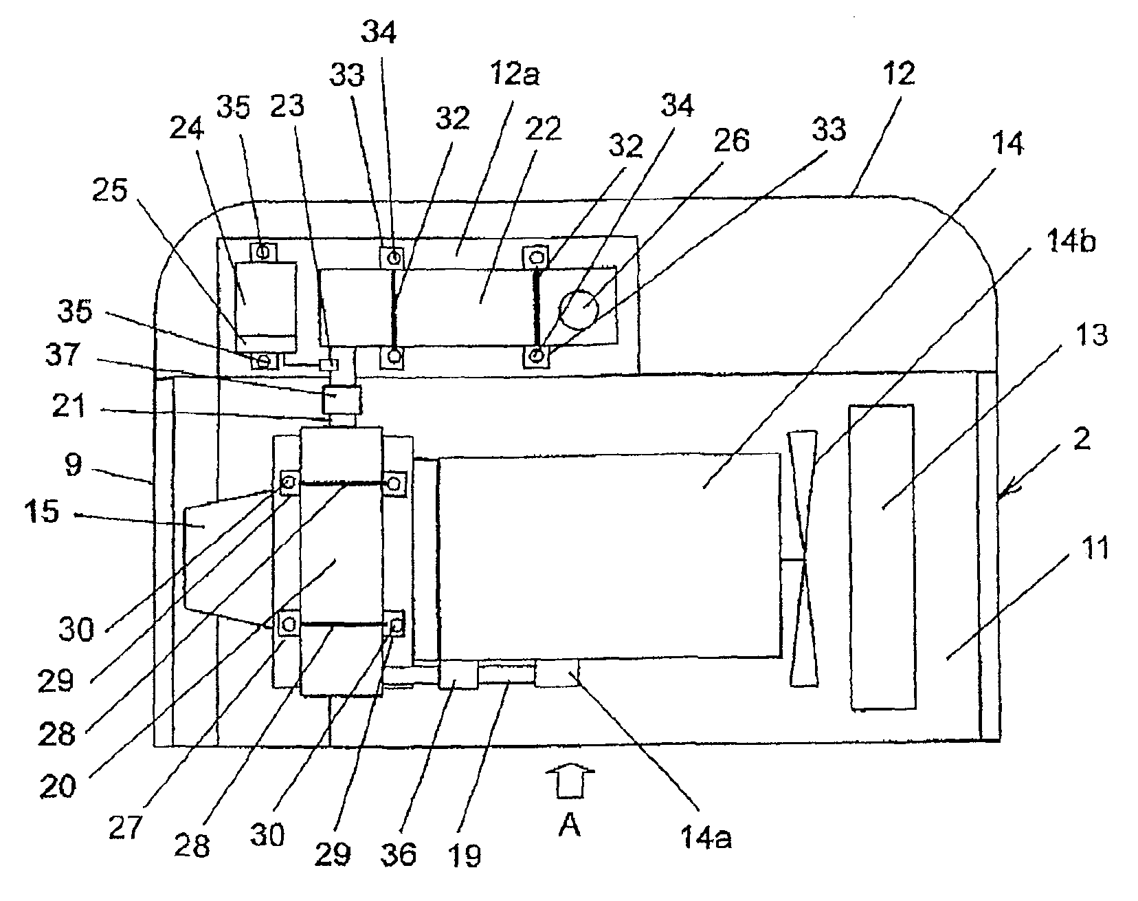
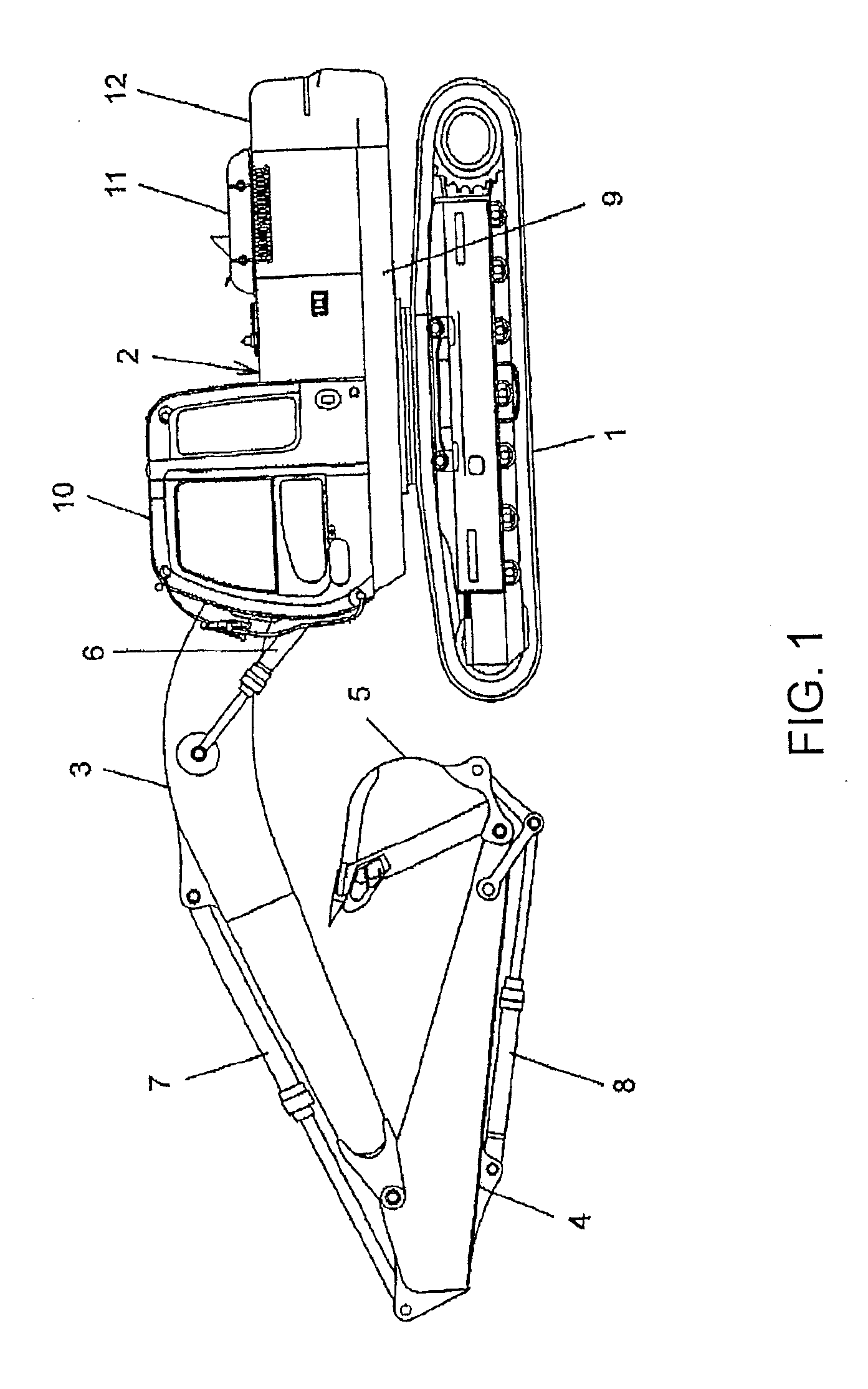
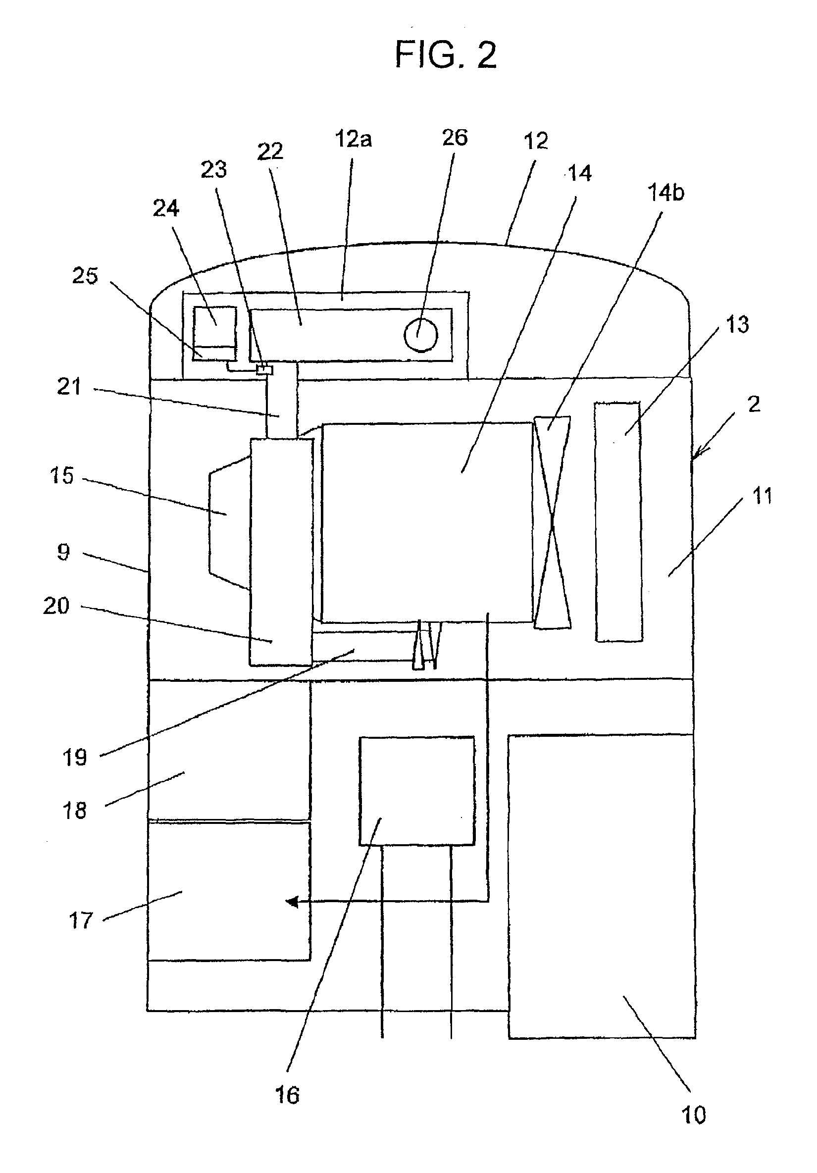
[0030]FIG. 1 is a side view showing a hydraulic excavator taken as one example of a construction machine on which an embodiment of the mounting structure according to the present invention for the NOx reduction system can be arranged; FIG. 2 is a plan view illustrating the outline construction of a revolving upperstructure arranged in the hydraulic excavator shown in FIG. 1; FIG. 3 is a plan view illustrating the mounting structure according to this embodiment for the NOx reduction system, which is arranged in the revolving upperstructure shown in FIG. 2; and FIG. 4 is a view as seen in the direction of arrow “A” in FIG. 3.

[0031]The construction machine to which the mounting structure of this embodiment for the NOx reduction system can be applied is, for example, the hydraul...


PUM

PropertyMeasurementUnit
stabilityaaaaaaaaaa
widthaaaaaaaaaa
temperatureaaaaaaaaaa

Abstract

A mounting structure is provided for an NOx reduction system for a hydraulic excavator. The NOx reduction system includes a PM collection filter to be arranged in an exhaust passage of an engine to collect suspended particulate matter in exhaust gas from the engine, a urea SCR catalyst for reducing and purifying nitrogen oxides in the exhaust gas from the engine, a urea water spay device for spraying a urea water into the exhaust passage of the engine, a urea water feeder for feeding the urea water to the urea water spray device, and a urea water storage tank for storing therein the urea water to be guided to the urea water feeder. In the mounting structure, the counterweight is provided with a recessed section formed therein, the urea SCR catalyst is arranged in the recessed section, and the PM collection filter is arranged in the engine compartment. The urea SCR catalyst and PM collection filter are arranged to form an “L” pattern.

Description

TECHNICAL FIELD[0001]This invention relates to a mounting structure for an NOx reduction system, which is to be arranged on a construction machine such as a hydraulic excavator and includes, as components, a PM collection filter for collecting suspended particulate mater contained in exhaust gas from an engine and a reduction catalyst for reducing and purifying nitrogen oxides (NOx) in the exhaust gas from the engine.BACKGROUND ART[0002]As a conventional technology of this sort, there is one disclosed in Patent Document 1. Disclosed in this Patent Document 1 are an NOx reduction system, which includes an upstream-side, first aftertreatment device for collecting particulates contained as suspended particulate matter in exhaust gas from an engine, that is, a PM collection filter and also a downstream-side, second aftertreatment device for purifying and detoxifying nitrogen oxide (NOx), that is, a reduction catalyst, and also a construction that the PM collection filter and the reducti...

Claims


Application Information

Patent Timeline
Patent Type & Authority Applications(United States)
IPC IPC(8): B60K13/04F01N3/10F01N3/00
CPCB01D2251/2067B01D2257/404B60K13/04E02F9/0883E02F9/18Y02T10/24F01N3/2066F01N2340/04F01N2590/08F01N2610/1406F01N3/021Y02T10/12Y02A50/20
Inventor KAMIYA, SHOHEI
Owner NIHON KENKI CO LTD
Why Eureka
Try Eureka