White LED lamp, backlight, light emitting device, display device and illumination device
a technology of led lamps and backlights, applied in the direction of discharge tubes luminescnet screens, semiconductor lasers, sustainable buildings, etc., can solve the problems of abnormal chromaticity, low light output of white led lamps, and damage to illuminated objects, so as to achieve excellent energy efficiency and energy-saving performance, the amount of uv light contained in the released light and the heat generated by the white led lamp is small, and the effect of reducing the effect of uv ligh
- Summary
- Abstract
- Description
- Claims
- Application Information
AI Technical Summary
Benefits of technology
Problems solved by technology
Method used
Image
Examples
first embodiment
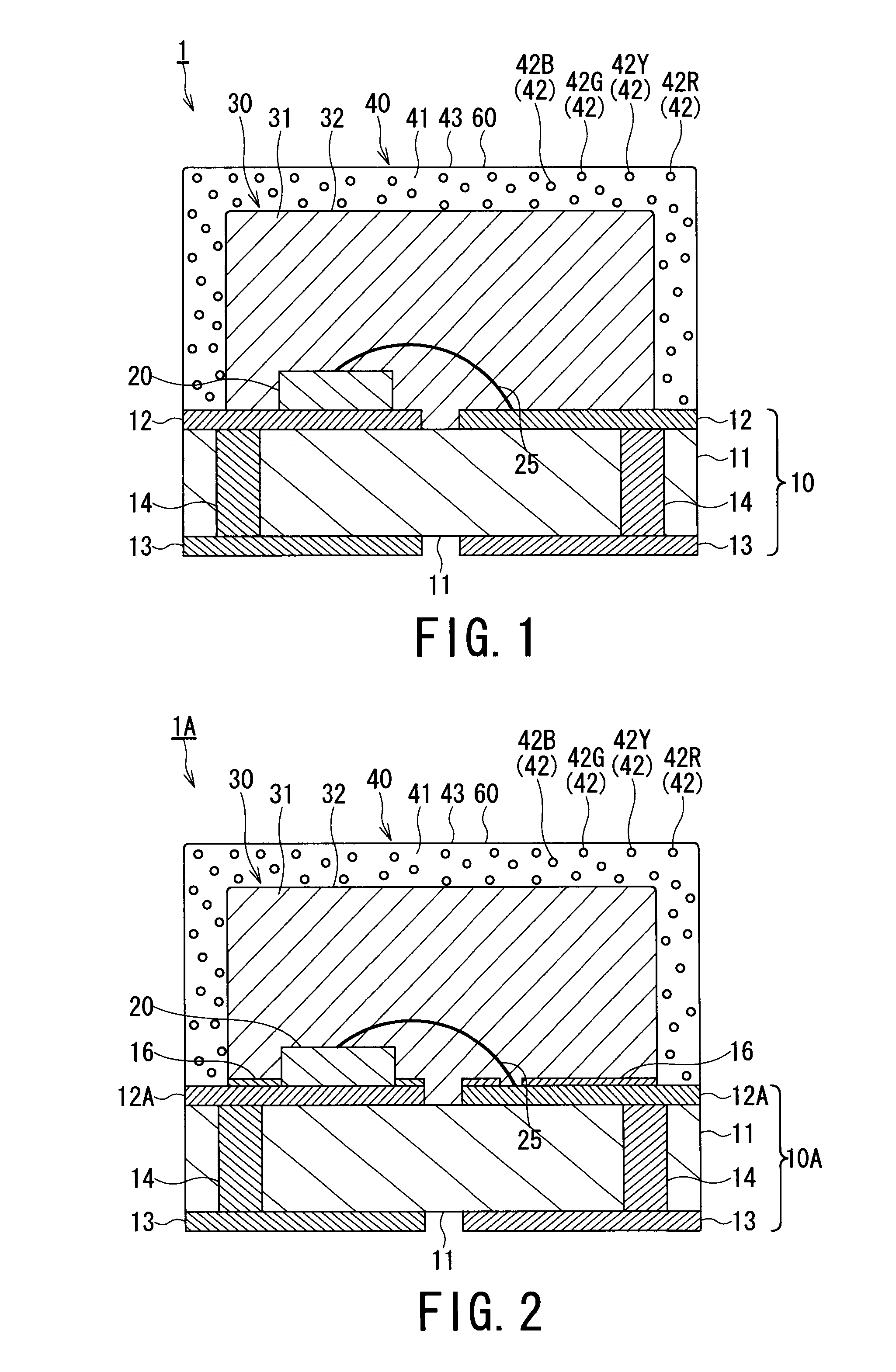
[0051]FIG. 1 is a cross sectional view schematically showing a first embodiment of a white LED lamp according to the present invention. As shown in FIG. 1, the white LED lamp 1 comprises: a substrate 10 provided with a front surface side electrode 12 as a conductive portion which is provided on an insulation portion 11; a light emitting diode chip mounted on the front surface side electrode 12 of the substrate 10; a transparent resin layer 30 for sealing the light emitting diode chip 20; and a phosphor layer 40 for covering the transparent resin layer 30.
[0052](Substrate)
[0053]The substrate 10 comprises: the insulation portion 11; the front surface side electrode 12 provided to the front side of the substrate 10 and a rear surface side electrode 13 provided to a rear surface side of the substrate 10; and a power-supplying via 14 passing through the insulation potion 11 so as to establish an electrical connection between the front surface side electrode 12 and the rear surface side e...
second embodiment
[0136]FIG. 2 is a cross sectional view schematically showing a structure of a second embodiment of the white LED lamp according to the present invention. The white LED lamp 1A of the second embodiment shown in FIG. 2 is configured by using a substrate 10A in place of the substrate 10 used in the white LED lamp 1 of the first embodiment shown in FIG. 1. Other elements of the white LED lamp 1A according to the second embodiments shown in FIG. 2 are the same as those of the white LED lamp 1 according to the first embodiments shown in FIG. 1. Therefore, the same reference numerals are used to denote the same members or elements as those of the first embodiment, and the detailed explanations of these members or elements are simplified or omitted hereunder.
[0137]In this second embodiment, the substrate 10A is used in place of the substrate 10, the front surface side electrode 12A is used in place of the front surface side electrode 12, and a light reflecting layer 16 is further formed to ...
third embodiment
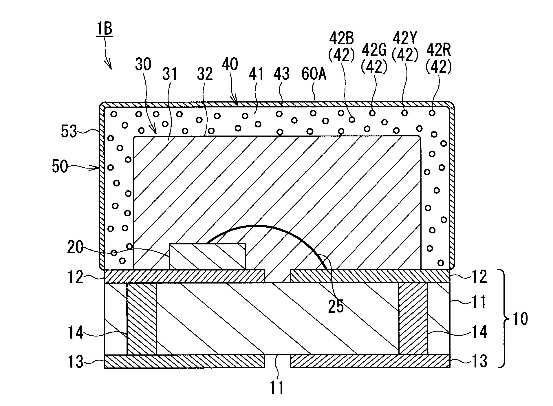
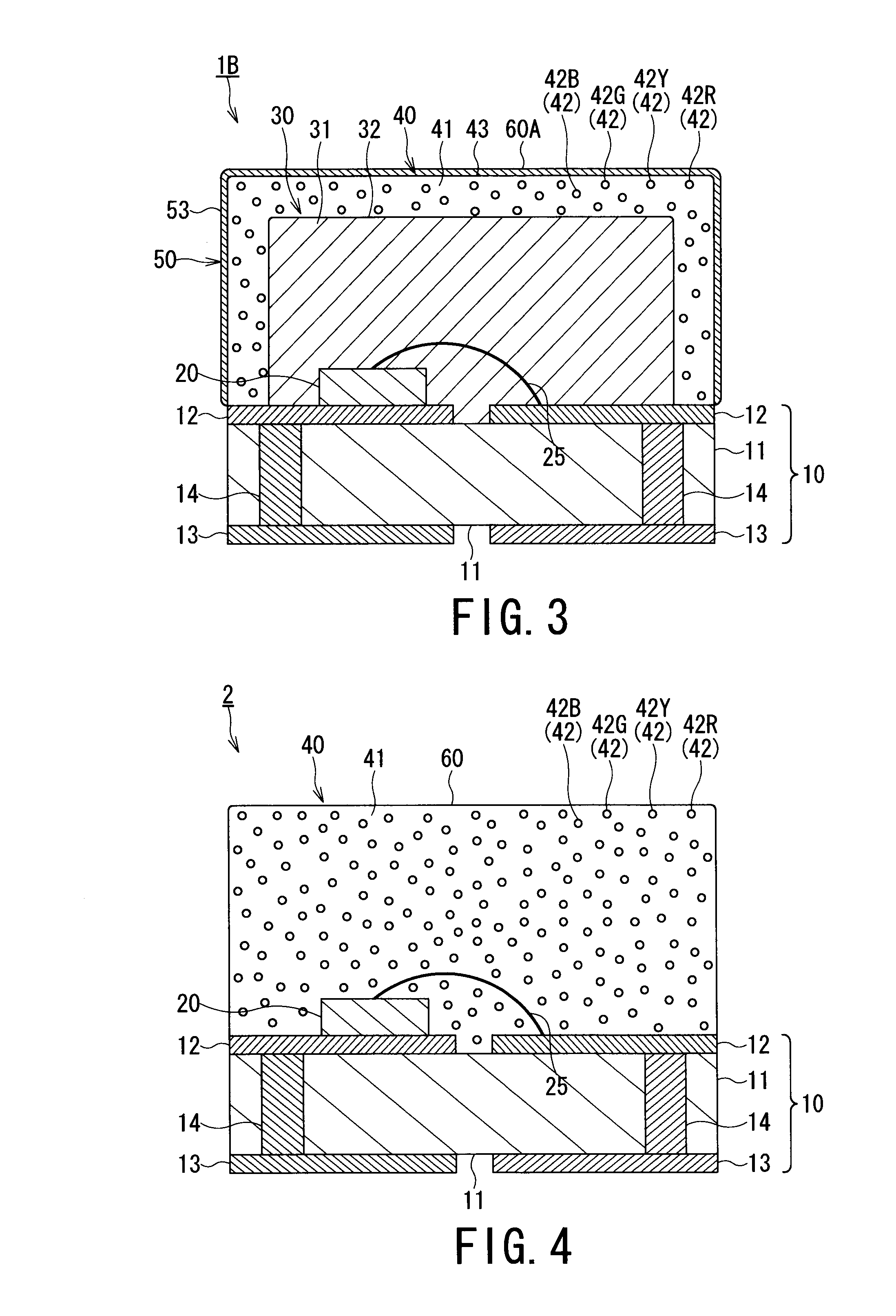
[0155]FIG. 3 is a cross sectional view schematically showing a structure of a third embodiment of the white LED lamp according to the present invention. With respect to the white LED lamp 1 of the first embodiment, the white LED lamp 1B of the third embodiment shown in FIG. 3 is configured to further form a UV absorbing layer 50 onto the surface of the phosphor layer 40.
[0156]Other elements of the white LED lamp 1B according to the third embodiments shown in FIG. 3 are the same as those of the white LED lamp 1 of the first embodiments shown in FIG. 1. Therefore, the same reference numerals are used to denote the same members or elements as those of the first embodiment, and the detailed explanations of these members or elements are simplified or omitted hereunder.
[0157]The UV light absorbing layer 50 is formed by dispersing UV light absorbing powder into a third transparent resin hardened substance (not shown).
[0158]The third transparent resin hardened substance is a product prepare...
PUM
 Abstract
Description
Claims
Application Information
 - R&D
- Intellectual Property
- Life Sciences
- Materials
- Tech Scout
- Unparalleled Data Quality
- Higher Quality Content
- 60% Fewer Hallucinations
Browse by: Latest US Patents, China's latest patents, Technical Efficacy Thesaurus, Application Domain, Technology Topic, Popular Technical Reports.
© 2025 PatSnap. All rights reserved.Legal|Privacy policy|Modern Slavery Act Transparency Statement|Sitemap|About US| Contact US: help@patsnap.com


