Coil selection for parallel magnetic resonance imaging

a magnetic resonance imaging and coil selection technology, applied in the direction of reradiation, measurement using nmr, instruments, etc., can solve the problems of memory storage and increased reconstruction tim

Active Publication Date: 2011-01-13
KONINKLIJKE PHILIPS ELECTRONICS NV
View PDF12 Cites 20 Cited by
  • Summary
  • Abstract
  • Description
  • Claims
  • Application Information

AI Technical Summary

Benefits of technology

[0008]The method according to the invention has the advantage, that in principle all possible subsets of coil element combinations are considered in order to select the most suitable set of coil elements for performing a magnetic resonance imaging scan of the region of interest. An exhaustive search through all possible subsets is not required since a SENSE (sensitivity encoding) reconstruction approach with Cartesian k-space sampling is performed and the projection matrix approach yields a recommendation for the optimal coil set to be used, which does not require a search for the most appropriate set of coil elements on a coil element by coil element basis.
[0022]In another aspect, the invention relates to a method of selecting a set of coil elements from a multitude of physical coil elements comprised in a coil array for performing a magnetic resonance imaging scan of a region of interest, wherein each physical coil element of the set of coil elements exhibits a coil sensitivity, wherein the method comprises determining a first estimated information content for the image resulting from magnetic resonance imaging scan of the region of interest, wherein the determination of that image is performed by combining the coil sensitivities of a first set of the physical coil elements. The method further comprises determining a second estimated information content for the image resulting from a magnetic resonance imaging scan of the region of interest, wherein the determination is performed by combining the coil sensitivities of a second set of the physical coil elements, wherein in the second set of the physical coil elements at least one coil is skipped compared to the first set of physical coil elements. Further, the loss of information resulting from skipping the at least one coil is calculated by comparing the first and second information content. Finally, the previous steps are repeated and the set of coil elements is determined which yields the minimum loss of information.

Problems solved by technology

The use of a large number of coil array elements can lead to memory storage problems and to increased reconstruction times.

Method used


Image

  • Coil selection for parallel magnetic resonance imaging
  • Coil selection for parallel magnetic resonance imaging
  • Coil selection for parallel magnetic resonance imaging

Examples


Embodiment Construction

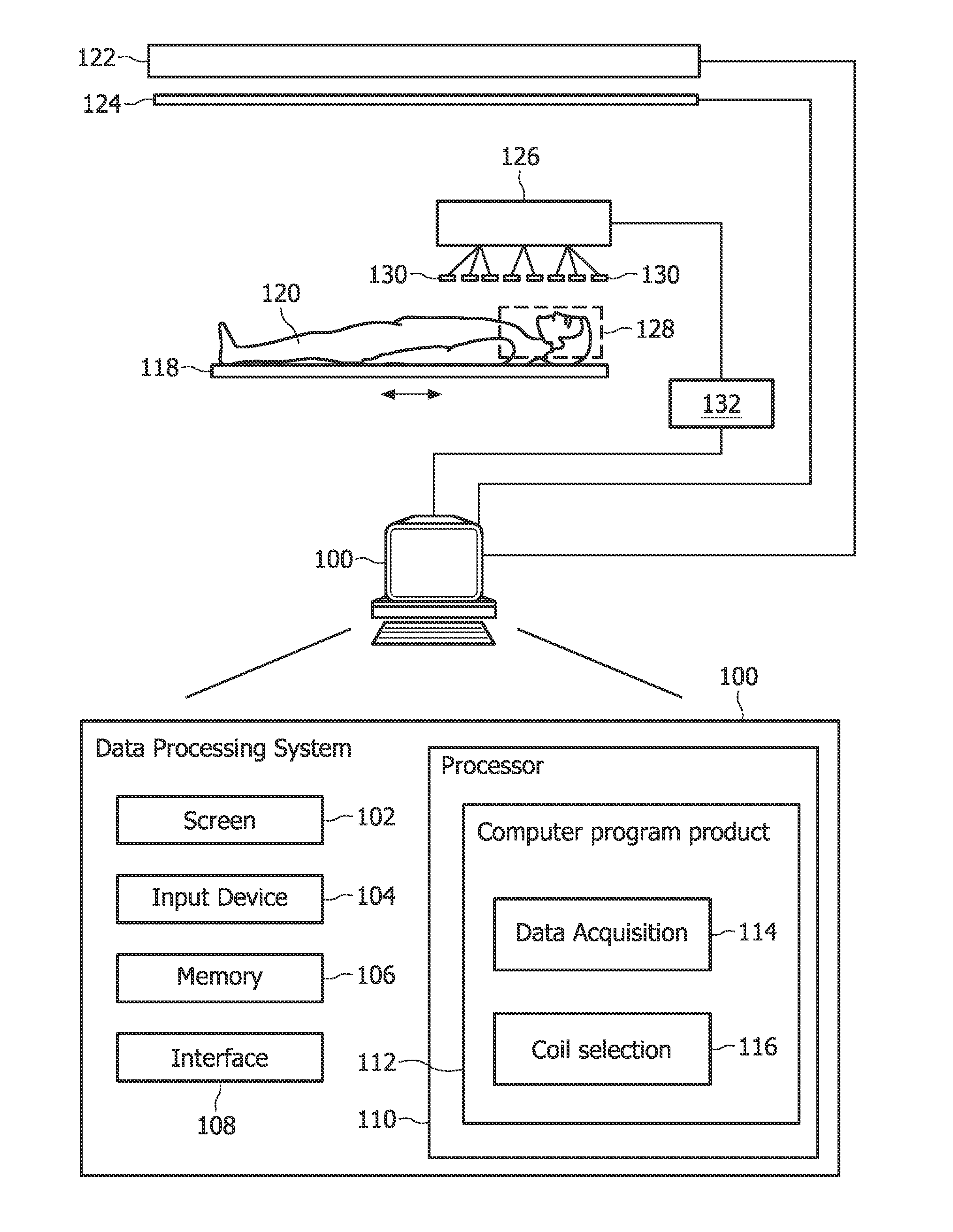
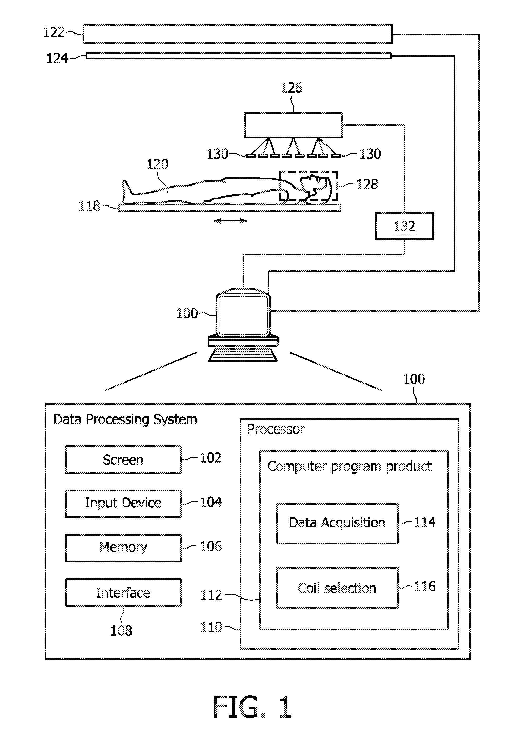
[0032]FIG. 1 is a schematic illustrating an MRI system according to the invention. Only major components of a preferred MRI system which incorporate the present invention are shown in FIG. 1. The magnetic resonance imaging apparatus comprises a data processing system 100, wherein the data processing system 100 typically comprises a computer screen 102 and an input device 104. Such an input device could be for example a keyboard or a mouse.

[0033]The MRI system in FIG. 1 further comprises a memory 106 and an interface 108. The interface 108 is adapted for communication and data exchange with typical hardware MRI components.

[0034]Typical hardware MRI components are for example a magnet 122 which generates a main magnetic field for performing a magnetic resonance imaging scan of an object 120, like for example a person. Further, gradient coils 124 are controlled by the data processing system 100, wherein the gradient coils are necessary and used for performing a 3-dimensional data acqui...


PUM


Abstract

The invention relates to a method of selecting a set of coil elements from a multitude of physical coil elements comprised in a coil array for performing a magnetic resonance imaging scan of a region of interest.

Description

TECHNICAL FIELD[0001]The invention relates to a method of selecting a set of coil elements from a multitude of physical coil elements comprised in a coil array for performing a magnetic resonance imaging scan, a computer program product and a magnetic resonance imaging system.BACKGROUND AND RELATED ART[0002]Parallel imaging using coil arrays with a large number of independent coil elements provides improved imaging performance and increased signal to noise ratio. Today, there is a fundamental trend to considerably increase the number of coil elements used for reception. Recently, 32-element coils have been introduced to boost SNR and to allow for higher reduction factors (Niendorf T., Hardy C. J., Giaquinto R. O., Gross P., Cline H. E., Zhu Y., Kenwood G., Cohen S., Grant A. K., Joshi S., Rofsky N. M., Sodickson D. K. (2006) Toward single breath-hold whole-heart coverage coronary MRA using highly accelerated parallel imaging with a 32-channel MR system. Magn Reson Med 56: 167-176).[...

Claims


Application Information

Patent Timeline
Patent Type & Authority Applications(United States)
IPC IPC(8): G01R33/44
CPCG01R33/022G01R33/3415G01R33/5659G01R33/543G01R33/5611G01R33/3664
Inventor JURRISSEN, MICHEL PAUL JURRIAANBOERNERT, PETERDONEVA, MARIYA IVANOVAFEDERER, MIHA
Owner KONINKLIJKE PHILIPS ELECTRONICS NV
Why Eureka
Try Eureka