Method for electroimpedance tomography

a tomography and electroimpedance technology, applied in the field of electroimpedance tomography, can solve the problems of inability to contact an electrode or a plurality of electrodes with the skin, and failure of current eit systems to deliver analyzable data in the disconnected cas

Inactive Publication Date: 2012-09-20
DRAGERWERK AG
View PDF1 Cites 11 Cited by
  • Summary
  • Abstract
  • Description
  • Claims
  • Application Information

AI Technical Summary

Benefits of technology

[0014]The advantage of the method according to the present invention is that usable EIT measurements can be carried out with such an EIT system with minimal loss of information even in case of a defect electrode. An EIT system or EIT device cannot measure without such a method at all, or if it can, an area-dependent loss of sensitivity is associated with the loss of the measurements, so that the reconstruction contains a fuzzy to blind area in the image depending on the underlying basic DAQ mode. The disturbance is greatest for the adjacent DAQ mode because of the high sensitivity and maximum data space; the disturbances should be smaller depending on the spread in DAQ modes with electrodes inbetween, which will hereinafter be called “spread,” because jumpovers are provided even in the standards. The disturbances may, in turn, cover wider spaces based on the typically poorer basic sensitivity and resolution with increasing spread. However, depending on the spread, even such DAQ modes benefit from the jumpover principle, because, as soon as the defect electrode is reached, information is regained due to the jumpover, instead of having to accept the loss of this measurement.
[0015]The data space is maximally utilized in the EIT device according to the present invention due to the jumpover current feed / voltage measurement, and the loss of information in the EIT image is minimized by a correspondingly adapted reconstruction, so that the EIT image continues to be able to be interpreted.

Problems solved by technology

However, the case in which electric contact of an electrode or of a plurality of electrodes with the skin is not possible, especially when an easy-to-handle electrode belt is used, where the electrode position cannot be changed as desired, for example, because of dressings or drains, may not infrequently occur in clinical practice.
The current EIT systems fail in these cases.
The current EIT systems never deliver analyzable data in the disconnected case, because neither data acquisition nor reconstruction are designed for the failure of electrodes.

Method used


Image

  • Method for electroimpedance tomography
  • Method for electroimpedance tomography
  • Method for electroimpedance tomography

Examples


Embodiment Construction

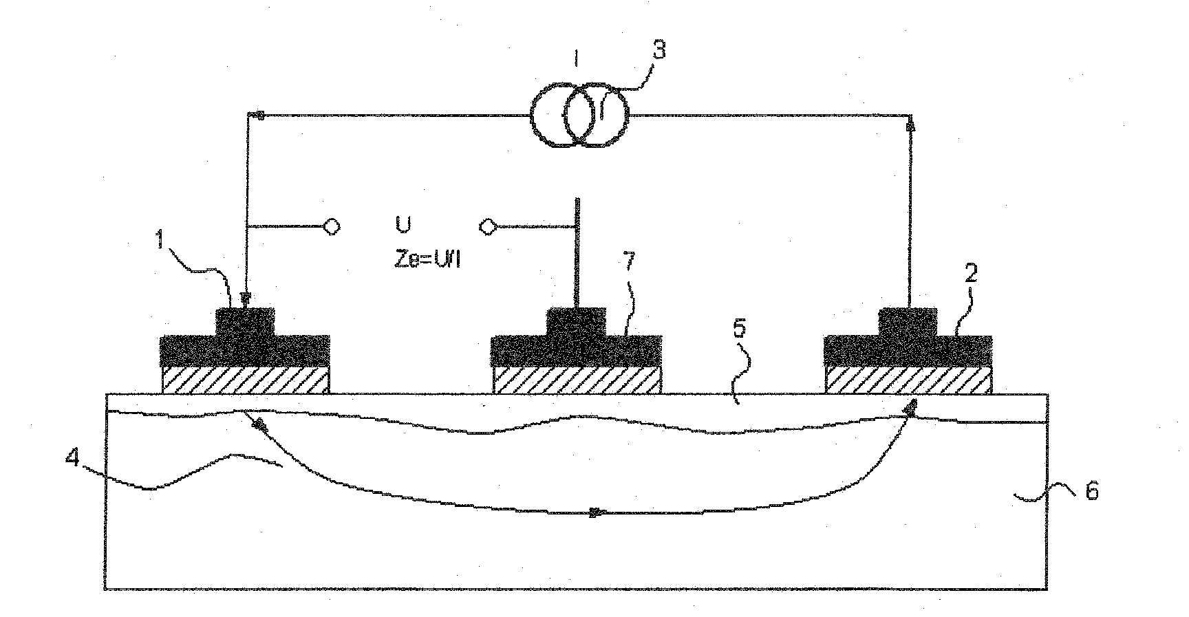
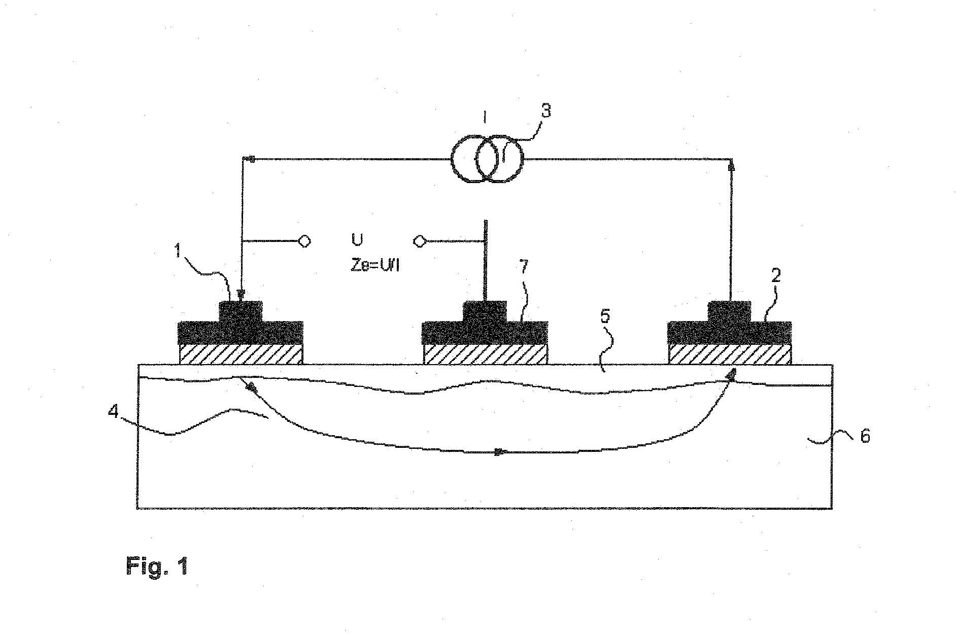
[0029]Referring to the drawings in particular, FIG. 1 schematically shows the principle of a three-point electrode-skin contact impedance measurement. The current I from a power source 3 is fed via two electrodes 1, 2. The current flows into the body 4 over an electrode 1 on the left and out again via an electrode 2 on the right. The body consists of upper skin layers 5 for contacting the electrodes 1, 2 and deeper skin and tissue layers 6. The voltage is measured from a current-carrying electrode against a currentless reference electrode. The main voltage drop at the current-carrying electrode 1 takes place at the transition to the interior of the body. The impedance is comparatively low in the body itself. The potential drop is measured against a currentless electrode 7, because there is no voltage drop here at the electrode-skin contact because I=0. The impedance Ze=U / I between the electrodes 1, 7 consequently represents essentially the electrode-skin contact transition impedance...


PUM


Abstract

A method for electroimpedance tomography makes possible an analysis and reconstruction of an image of the electric resistance in the presence of a defect electrode (A). The method includes the steps of identifying an electrode as a defect electrode (A), which has no contact with the body, by means of an impedance measurement, of performing current feeds such that at least the defect electrode (A) is jumped over, and of determining voltage potentials in the area of the defect electrode (A) over the defect electrode (A) in such a way that the defect electrode (A) is jumped over at least once.

Description

CROSS REFERENCE TO RELATED APPLICATIONS[0001]This application claims the benefit of priority under 35 U.S.C. §119 of German Patent Application DE 10 2011 014 107.3 filed Mar. 16, 2011, the entire contents of which are incorporated herein by reference.FIELD OF THE INVENTION[0002]The present invention pertains to a method for electroimpedance tomography.BACKGROUND OF THE INVENTION[0003]Electroimpedance tomography (EIT) is increasingly used in medicine. Typical EIT devices use 8, 16 or 32 electrodes for data acquisition, current being fed through two electrodes and the resulting voltage being measured between the remaining electrodes. By combining different feeds and measurements, it is possible to generate a signal vector, from which the impedance distribution can be determined by means of a suitable algorithm or the relative change in the impedance distribution relative to a reference value can be determined in the electrode plane in functional EIT (fEIT). The latter method is used i...

Claims


Application Information

Patent Timeline
Patent Type & Authority Applications(United States)
IPC IPC(8): A61B5/053
CPCA61B5/0536A61B2562/04A61B2560/0276
Inventor GARBER, YVOGALLUS, THOMAS
Owner DRAGERWERK AG
Why Eureka
Try Eureka