Method and device for measuring a sample in an NMR spectrometer using a coupling configuration with a press fit cell having a capillary envelope fastener

a coupling configuration and nmr spectrometer technology, applied in the direction of geological measurements, component separation, reradiation, etc., can solve the problems of inability to measure samples in a spectrometer, high mounting cost, time-consuming, etc., and achieve good elastic deformation properties, prevent inadvertent contact with users, and easy perception of the overall capillary

Inactive Publication Date: 2011-01-13
BRUKER BIOSPIN
View PDF4 Cites 6 Cited by
  • Summary
  • Abstract
  • Description
  • Claims
  • Application Information

AI Technical Summary

Benefits of technology

[0011]In the inventive coupling configuration, the supply capillary is secured twice in the coupling element. The end of the supply capillary is clamped directly in the funnel-shaped section after axial insertion, and forms a first holding ring. The end of the supply capillary is thereby slightly elastically compressed in a radial direction, thereby increasing the adhesive or frictional force.
[0024]In an alternative further development, the funnel-shaped section and the further funnel-shaped section terminate in a cell having a diameter which is larger than the narrowest diameters of the funnel-shaped sections. The cell can be used as a sample space to perform a measuring operation, e.g. spectroscopic measurement. For this reason, the sample volume in the sample space is increased.

Problems solved by technology

The construction of a transition from one capillary to another capillary, or another means to which the liquid test sample is to be supplied, is thereby particularly difficult to realize.
Mounting is generally quite expensive and time-consuming, and moreover susceptible to damage.
If the capillary is damaged, e.g. broken, it must be repaired by experts, which is expensive.
This type of mounting, however, bears the danger that the capillary is not sufficiently fixed in the coupling element and might be inadvertently removed from the coupling element.
Damage to a capillary, in particular breakage in the vicinity of the coupling element, could also easily happen.

Method used


Image

  • Method and device for measuring a sample in an NMR spectrometer using a coupling configuration with a press fit cell having a capillary envelope fastener
  • Method and device for measuring a sample in an NMR spectrometer using a coupling configuration with a press fit cell having a capillary envelope fastener
  • Method and device for measuring a sample in an NMR spectrometer using a coupling configuration with a press fit cell having a capillary envelope fastener

Examples


Embodiment Construction

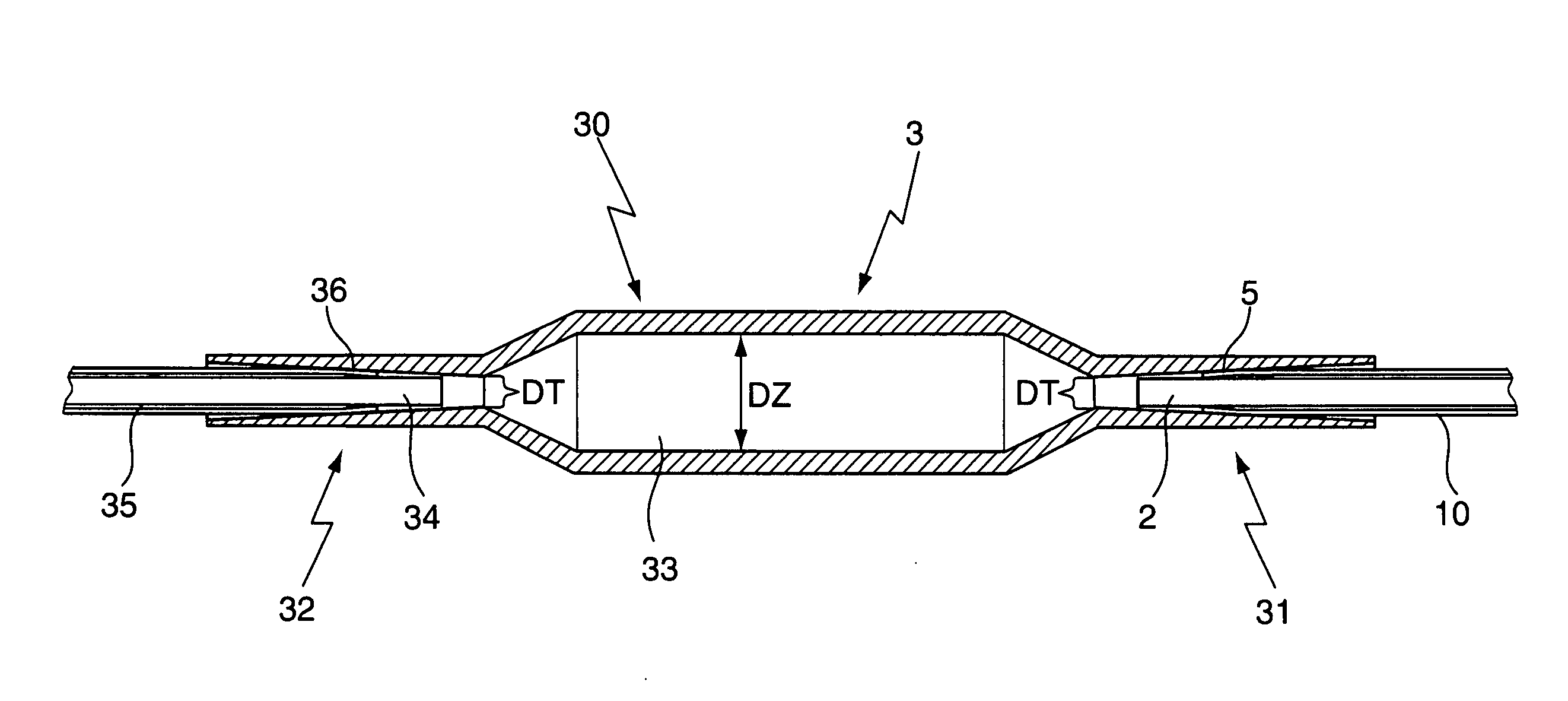
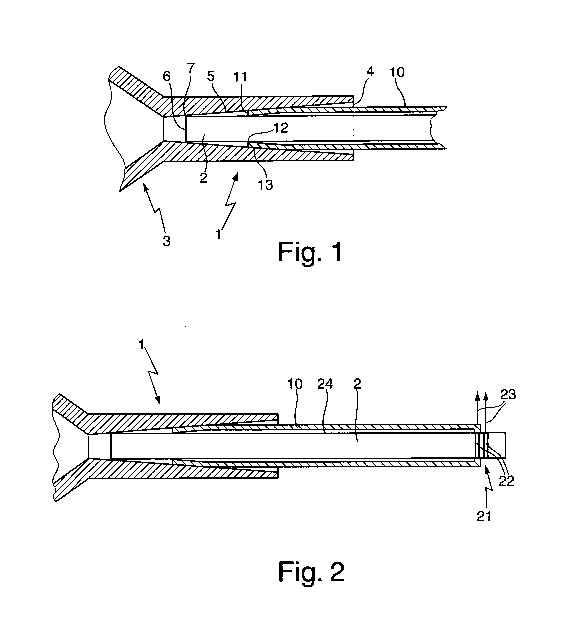
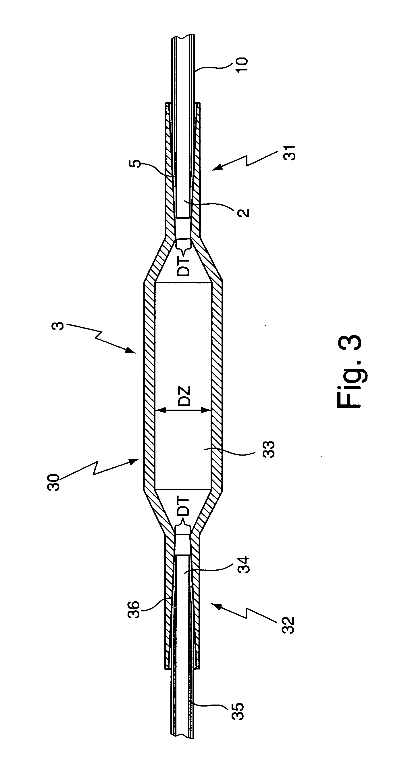
[0032]FIG. 1 shows a schematic cross-section through an inventive coupling configuration 1. The coupling configuration 1 comprises a supply capillary 2 and a coupling element 3 (marked with hatched lines) to which the supply capillary 2 is connected, and an envelope capillary 10 which surrounds the supply capillary 2 and is also connected to the coupling element 3.

[0033]The coupling element 3 has an opening 4 which merges into a funnel-shaped section 5. The funnel-shaped section 5 conically tapers from the opening 4, wherein the inner diameter linearly decreases with increasing depth (the funnel-shaped section 5 is therefore suitable for clamping a plurality of capillary diameters). Alternatively, the funnel-shaped section may also have a different tapering geometry.

[0034]The supply capillary 2 has been inserted and pressed into the funnel-shaped section 5 (in the present case towards the left, into the funnel-shaped section 5) such that an end 6 of the supply capillary 2 is clamped...


PUM


Abstract

A method for measuring an sample in an NMR spectrometer uses a coupling configuration (1; 30) comprising a coupling element (3) and a supply capillary (2), wherein the coupling element (3) has a funnel-shaped section (5) which clamps an end (6) of the supply capillary (2). An envelope capillary (10) is provided into which the supply capillary (2) is inserted, wherein the end (6) of the supply capillary (2) projects past an end (11) of the envelope capillary (10), and the end (11) of the envelope capillary (10) is also clamped in the funnel-shaped section (5).

Description

[0001]This application is a continuation of Ser. No. 11 / 812,821 filed Jun. 22, 2007 and claims Paris Convention priority of DE 10 2006 029 496.3 filed Jun. 27, 2006 the complete disclosures of which are hereby incorporated by reference.BACKGROUND OF THE INVENTION[0002]The invention concerns a coupling configuration comprising a coupling element and a supply capillary, wherein the coupling element has a funnel-shaped section which clamps an end of the supply capillary.[0003]A coupling means of this type is disclosed in the catalogue of Polymicro Technologies, LLC, PT-MLC / 03-02, “Inner-Lok” of 2002.[0004]Capillaries (supply capillaries) are used to supply liquid samples to a measuring apparatus, e.g. a gas chromatography system or an NMR spectrometer. These capillaries are usually produced from fused silica to ensure good chemical resistance of the capillary to the test sample or its solvent. The sample is thereby mostly pushed along by a downstream transport liquid, e.g. pure solvent...

Claims


Application Information

Patent Timeline
Patent Type & Authority Applications(United States)
IPC IPC(8): G01R33/48
CPCB01L3/565B01L2300/02B01L2300/0838G01R33/307G01N30/6039G01N30/6078G01N30/6026
Inventor HOFMANN, MARTINMARQUARDSEN, THORSTEN
Owner BRUKER BIOSPIN
Why Eureka
Try Eureka