
Lighting device and display device having the same

a technology of display device and light source, which is applied in the direction of static indicating device, discharge tube/lamp details, instruments, etc., can solve the problems of color irregularity of backlight, achieve high-quality images, reduce color irregularity, and accurate brightness control

Inactive Publication Date: 2011-01-13
SHARP KK
View PDF10 Cites 21 Cited by
  • Summary
  • Abstract
  • Description
  • Claims
  • Application Information

AI Technical Summary

Benefits of technology

[0011]According to the present invention, it is possible to reduce color irregularity and brightness irregularity of light to be irradiated from light sources effectively even if a light-emitting element included in the light sources fails to light properly.
[0012]Further, by using the lighting device according to the present invention as a backlight that irradiates a display portion with light, it is possible to realize a display device that can display a high-quality image as a result of accurate brightness control that reduces color irregularity and brightness irregularity of a display image effectively even if a light-emitting element included in the light sources of the lighting device fails to light properly.

Problems solved by technology

Accordingly, if an LED of any one of the colors is open and fails to light properly, the relevant light source loses its luminescent color balance and is no longer a white light source, which results in color irregularity of the backlight.

Method used


Image

  • Lighting device and display device having the same
  • Lighting device and display device having the same
  • Lighting device and display device having the same

Examples


embodiment

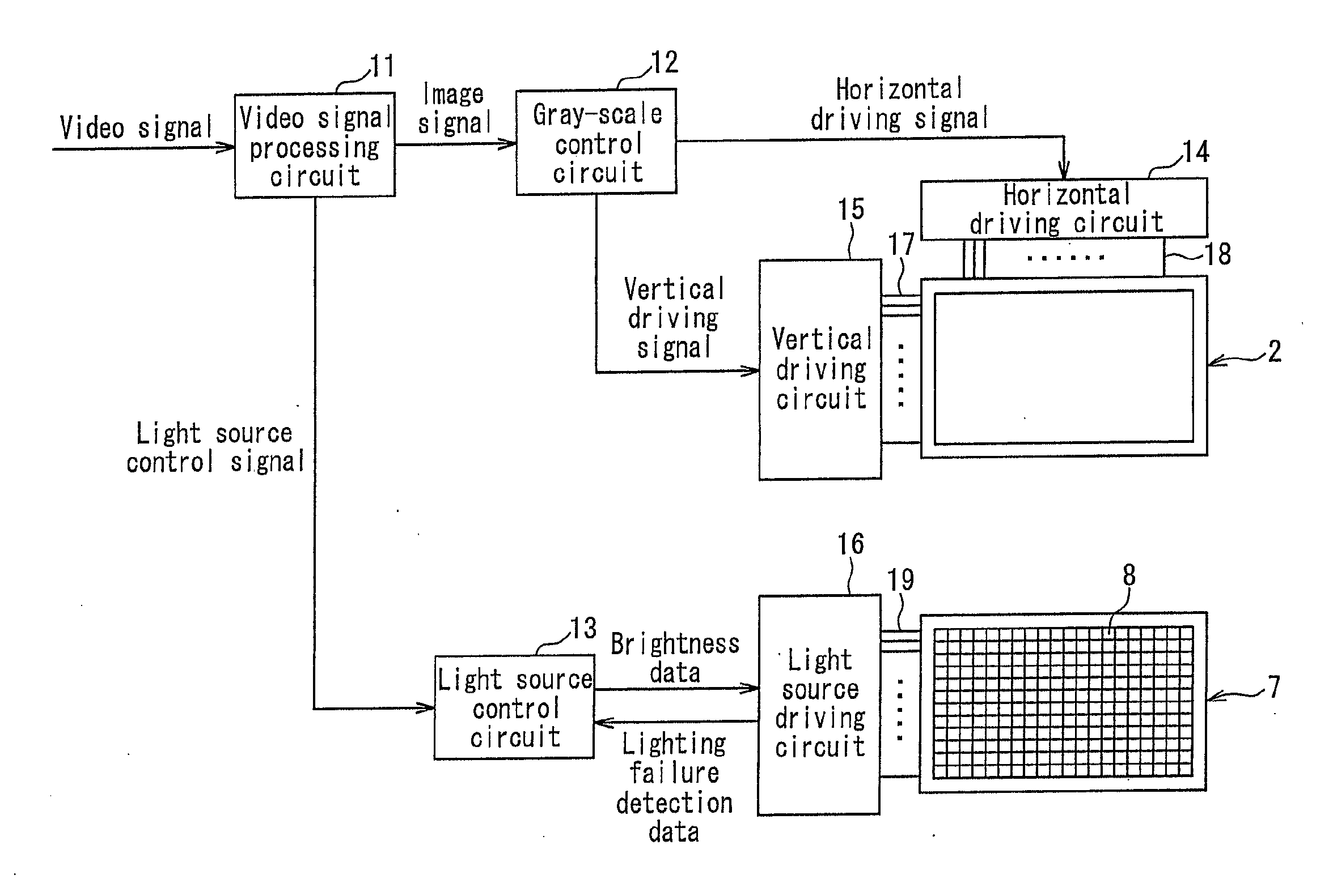
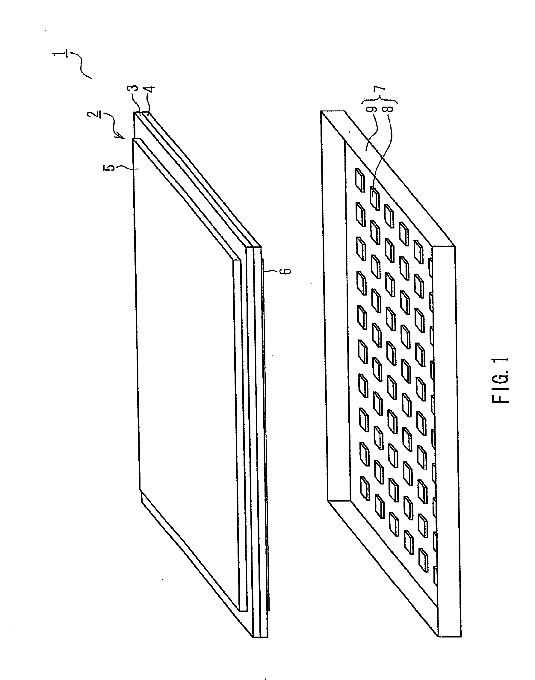
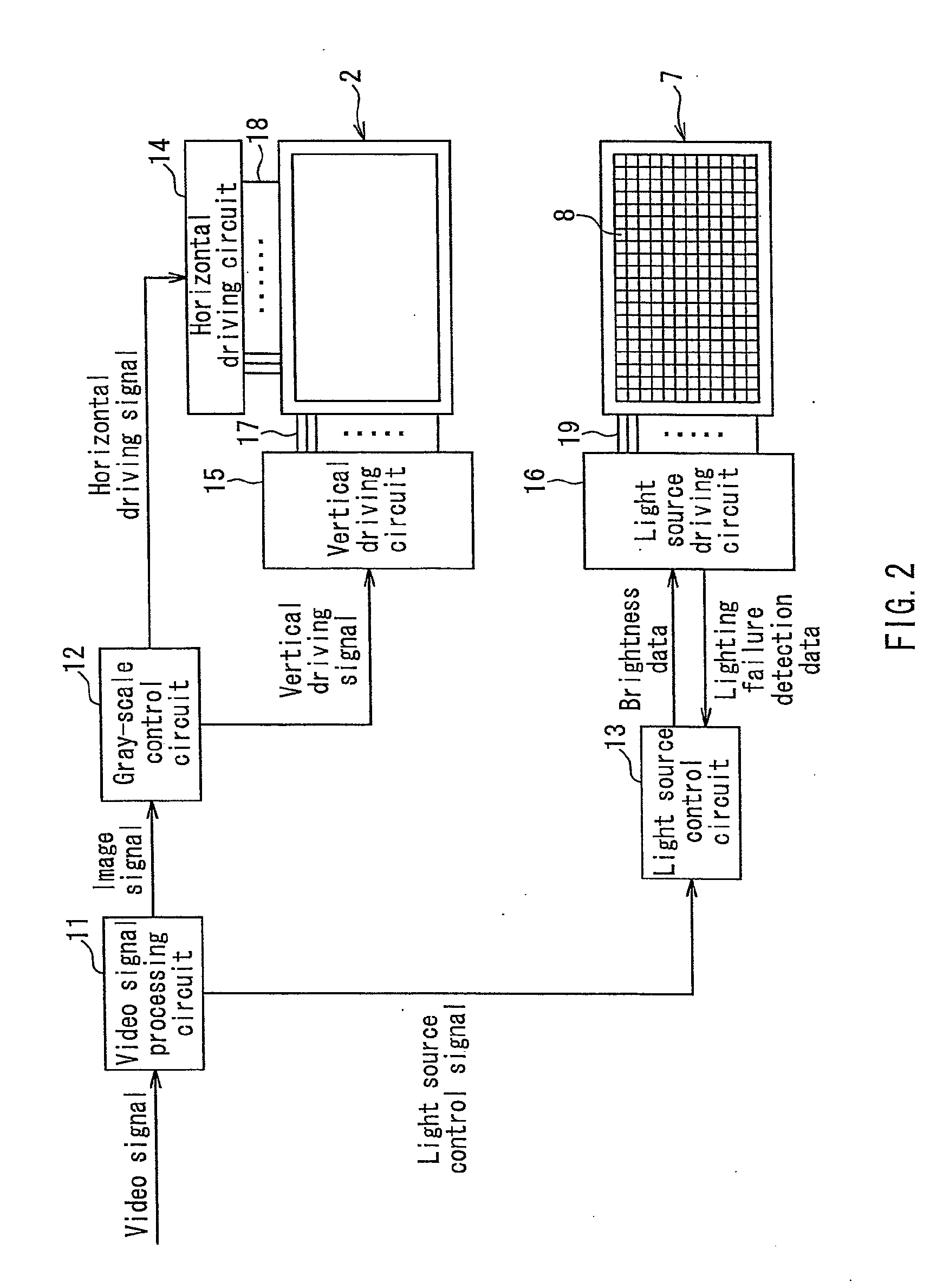
[0039]FIG. 1 is an exploded perspective view showing a schematic configuration of a display device according to an embodiment of the present invention. As shown in FIG. 1, a liquid crystal display device 1 according to the present embodiment includes a liquid crystal panel 2 as a display portion, and a backlight 7 as a lighting device that irradiates transmission light required for image display on the liquid crystal panel 2. It should be noted that a video display circuit for performing signal processing for displaying an image, a control circuit for locally adjusting the coloration and brightness of the backlight as an active backlight, a driving circuit, and the like are not shown in FIG. 1.

[0040]The liquid crystal panel 2 is a transmission type display element that displays an image by controlling the amount of light to be transmitted through pixels. The type of the liquid crystal panel 2 is not limited particularly as long as multi-gray-scale image display is possible, and may ...


PUM


Abstract

There is provided a lighting device that can reduce the occurrence of both color irregularity and brightness irregularity of light to be irradiated onto an irradiation surface even if one of a plurality of light-emitting elements included in light sources fails to light properly, and a display device using this lighting device. The lighting device includes a plurality of light sources (8), each having a plurality of light-emitting elements (26) of different luminescent colors, arranged on a plane, and can control color and luminance of light to be irradiated from the light sources (8) by controlling brightness of each of the light-emitting elements (26) based on a light source driving signal. The device includes: a lighting failure detecting portion (23) that detects which of the light-emitting elements (26) fails to light properly; an emission correction determining portion (34) that determines the necessity of brightness correction for the light-emitting elements (26) other than the light emitting element (26) that fails to light properly, based on a level of the brightness instructed for the light-emitting element (26) that fails to light properly by the light source driving signal; and an emission correcting portion (35) that performs the brightness correction for the other light-emitting elements in accordance with the determination made by the emission correction determining portion (34).

Description

TECHNICAL FIELD[0001]The present invention relates to a lighting device including a plurality of light sources, each having a plurality of light-emitting elements, arranged on a plane, and a display device using the lighting device as a backlight. In particular, the present invention relates to a lighting device that is less likely to cause color irregularity and brightness irregularity of light to be irradiated from light sources even if a light-emitting element fails to light properly, and a display device having the same.BACKGROUND ART[0002]In recent years, a liquid crystal display device characterized by low power consumption, thinness, light weight, and the like has been used widely as a display device for television receivers and the like. A liquid crystal panel used as a display portion of the liquid crystal display device is a so-called non-light-emitting type display element that does not emit light by itself. Thus, the liquid crystal display device usually includes a plane...

Claims


Application Information

Patent Timeline
Patent Type & Authority Applications(United States)
IPC IPC(8): G09G5/10H05B37/03
CPCG09G3/3413G09G3/3426G09G3/3648G09G2320/0242G09G2320/0633G09G2320/064H05B37/036G09G2320/0666G09G2330/021G09G2330/08G09G2360/16H05B33/083H05B33/089G09G2320/0646H05B45/50H05B47/23H05B45/48
Inventor NAKAZAWA, KENYAMAMOTO, MANABUFUJIWARA, KOHJIOKUDA, SHINYA
Owner SHARP KK
Learn More