
Method for filling a ball roller bearing with roll bodies as well as a ball roller bearing filled according to the method

Inactive Publication Date: 2011-01-13
SCHAEFFLER TECH AG & CO KG
View PDF5 Cites 3 Cited by
  • Summary
  • Abstract
  • Description
  • Claims
  • Application Information

AI Technical Summary

Benefits of technology

[0008]Proceeding from the described disadvantages of the solutions of the known prior art, the object of the invention is therefore to devise a method for filling a ball roller bearing with rolling elements, enabling a ball roller bearing designed with similar raceway dimensions to a comparable deep-groove ball bearing to be filled with a substantially greater number of ball rollers, so that a ball roller bearing filled according to this method is primarily distinguished by a greater radial load-bearing capacity and by a substantially increased service life.DESCRIPTION OF THE INVENTION
[0020]In a further appropriate development of the method according to the invention in claim 6 an annular support plane arranged between the bearing rings is used for temporarily holding the inserted ball rollers and for orienting them horizontally level in the distance between the bearing rings. This support plane is arranged in one plane with the lower edge of the raceway of the outer bearing ring and thereby ensures that the inserted ball rollers do not slip through between the bearing rings, but after initially sliding along on and out of the raceway of the inner bearing ring settle on this support plane, so that the ball rollers with their bearing surfaces automatically tilt into both raceways of the bearing rings and, as further ball rollers are inserted, in this position roll along on the support plane into the free filling space located on both sides of the insertion point. As the number of inserted ball rollers increases, the inner bearing ring is in the process gradually pushed back out of its initial eccentric limit position by the ball rollers, so that after insertion of the last ball roller the radial offset of the inner bearing ring is completely cancelled and the two bearing rings are again arranged concentrically with one another. This support plane has furthermore proved very helpful when, after the rotational acceleration of the outer bearing ring, both bearing rings are axially lowered, in order to move the inserted ball rollers into a horizontally level position in the raceways, since this support plane, due to the axial lowering of the bearing rings, then projects into the interior of the ball roller bearing in such a way that it forms a supporting surface for the ball rollers now resting on this with one lateral face, which serves to orient the ball rollers horizontally and to prevent any rotation of the ball rollers when subsequently inserting the bearing cage.

Problems solved by technology

In practice it has proved, however, that limits are nevertheless placed on the load-bearing capacity of such deep-groove ball bearings, owing to the low maximum number of balls that can be fitted or the low maximum filling density of approximately 60%.
Both in the unclosed and in the closed embodiment, however, such insertion apertures have the disadvantage that due to their wedge-shaped opening into the raceways of the balls or due to burrs a “sticking” or jamming of the rolling elements can occur at this insertion aperture, so that in practice such solutions have failed to gain acceptance.
Despite the possibility for inserting these specially designed ball rollers axially into the bearing, thereby allowing the radial rolling bearing to be filled with a large number of rolling elements, however, such a radial rolling bearing at most only represents a compromise in terms of the desired increase in the load-bearing capacity of the bearing.

Method used


Image

  • Method for filling a ball roller bearing with roll bodies as well as a ball roller bearing filled according to the method
  • Method for filling a ball roller bearing with roll bodies as well as a ball roller bearing filled according to the method
  • Method for filling a ball roller bearing with roll bodies as well as a ball roller bearing filled according to the method

Examples


Embodiment Construction

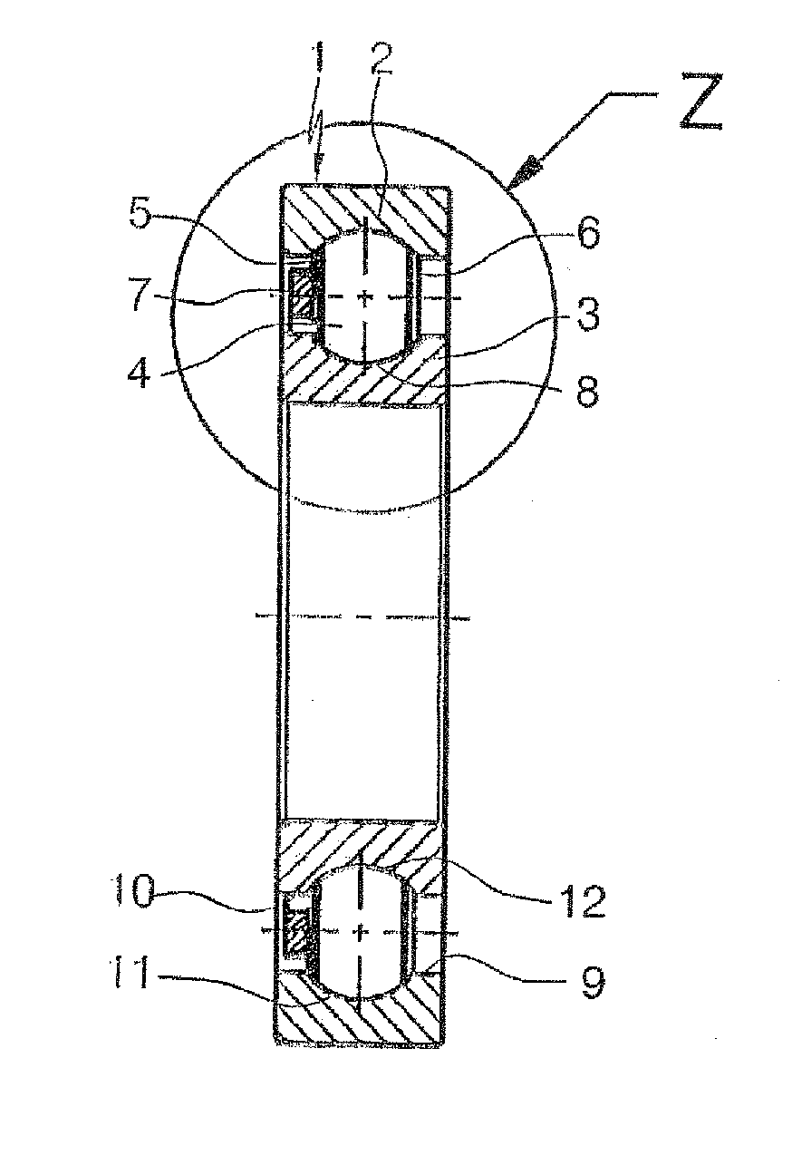
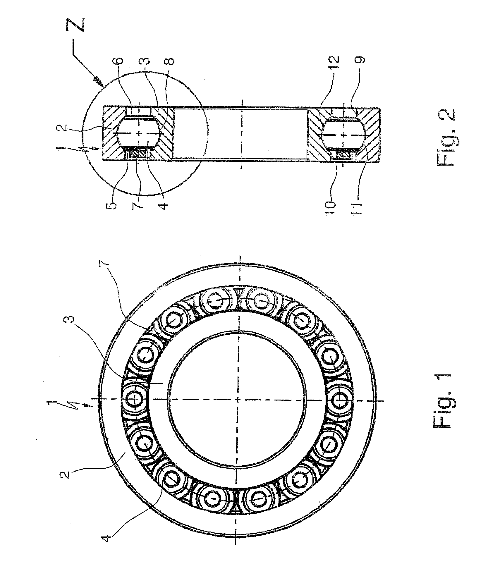
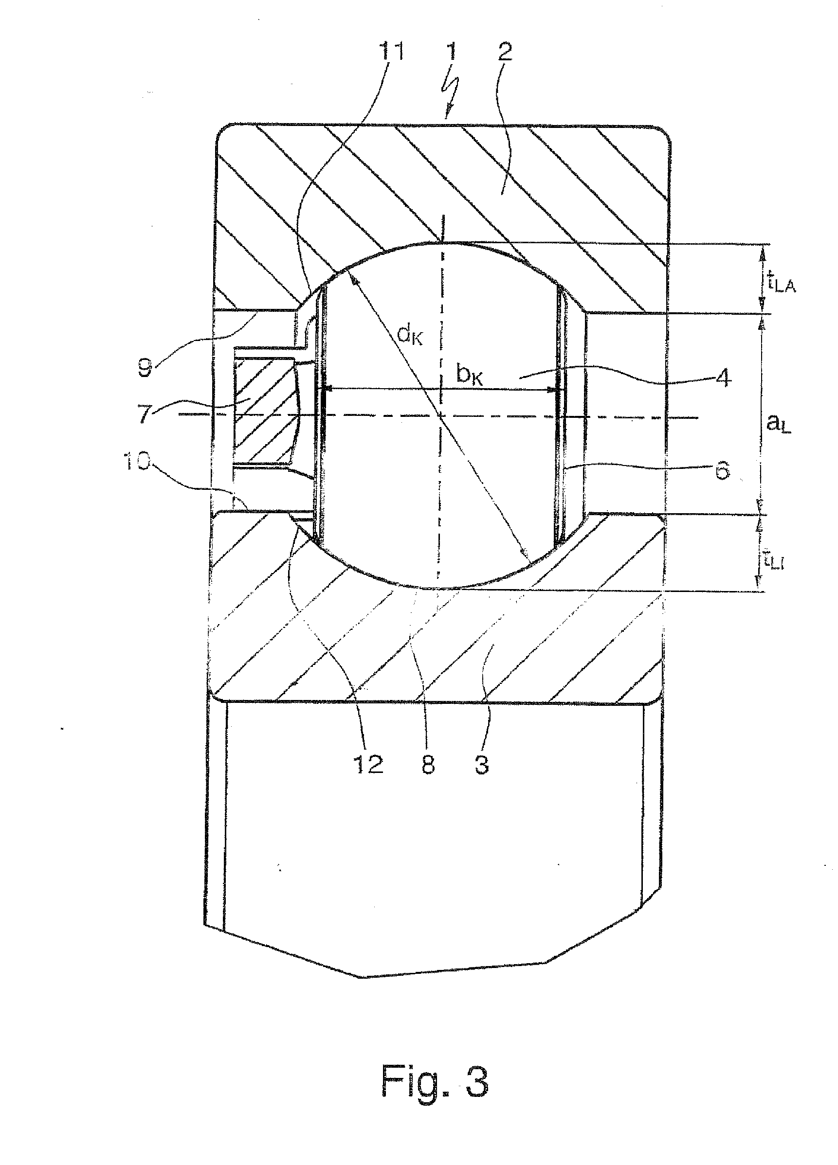
[0009]According to the invention this object is achieved, in a ball roller bearing having the features of the preamble part of claim 1, by an axial-tilt eccentric assembly method of the ball rollers through the distance between the bearing rings, in which the inner bearing ring of the two bearing rings, arranged in a horizontal concentric position relative to one another, is arranged so that firstly it is slightly moveable radially along a bearing longitudinal central axis and secondly it is on an axially offset higher plane than the outer bearing ring, in order to create a distance between the bearing rings that is greater than the width of the ball rollers, and the insertion of the ball rollers is performed by the following steps:[0010]a) radial displacement of the inner bearing ring into an eccentric limit position and feeding of the ball rollers with their lateral faces oriented towards the bearing rings to the site of the maximum distance between the bearing rings on the bearin...


PUM

PropertyMeasurementUnit
Fractionaaaaaaaaaa
Fractionaaaaaaaaaa
Fractionaaaaaaaaaa

Abstract

A method for filling a ball roller bearing with roll bodies, and a ball roller bearing, which is filled according to the method and has an outer and an inner bearing ring and a plurality of ball rollers, which are arranged between these bearing rings and have two side surfaces, which are flattened symmetrically from a basic spherical shape, parallel to one another and held at uniform distances from one another by a bearing cage. The ball rollers roll in groove-shaped raceways recessed in the inner face of the outer bearing ring and the outer face of the inner bearing ring. The ball roller bearing is filled by an eccentric axial, tilting fitting of the ball rollers through the interval between the bearing rings in the form, that the filled ball roller bearing is filled to the extent of about 94% and has a service life of up to 253%.

Description

FIELD OF THE INVENTION[0001]The invention relates to a method for filling a ball roller bearing having the features of the preamble part of claim 1 with rolling elements, and to a ball roller bearing filled by the method, which can be used to particular advantage, for example, as a fixed bearing for the drive and output shafts of a motor vehicle manual transmission.BACKGROUND OF THE INVENTION[0002]In rolling bearing technology it is commonly known that deep-groove ball bearings are rigid, permanently assembled radial rolling bearings, which are distinguished by an equally high radial and axial load bearing capacity, and which by virtue of their low friction have the highest speed limits of all types of bearings. These deep-groove ball bearings substantially comprise an outer bearing ring and an inner bearing ring and a number of balls, which as rolling elements are arranged between the bearing rings and which roll on groove-shaped ball raceways recessed into the inside of the outer ...

Claims


Application Information

Patent Timeline
IPC IPC(8): F16C43/04F16C33/48
CPCF16C33/36F16C43/04F16C43/06Y10T29/49696Y10T29/49648Y10T29/49643Y10T29/49636F16C23/10F16C19/26F16C2361/61
Inventor DOEPPLING, HORSTGEIGER, ERNSTHOFMANN, HEINRICHMUSER, JOACHIM
Owner SCHAEFFLER TECH AG & CO KG
Features
  • Generate Ideas
  • Intellectual Property
  • Life Sciences
  • Materials
  • Tech Scout
  • Unparalleled Data Quality
  • Higher Quality Content
  • 60% Fewer Hallucinations
Learn More