Dust collecting attachment

a technology for dust collecting and power tools, applied in the field can solve the problems of user having to take the trouble, and achieve the effect of improving the usability of dust collecting attachments for power tools

Active Publication Date: 2011-01-13
MAKITA CORP
View PDF11 Cites 42 Cited by
  • Summary
  • Abstract
  • Description
  • Claims
  • Application Information

AI Technical Summary

Benefits of technology

[0006]Accordingly, it is an object of the invention to improve a usability of a dust collecting attachment for a power tool.
[0010]The dust collecting member according to the invention has an opening formed in a region which faces the operating member for removal and / or bit angle adjustment of a tool bit in the state in which the dust collecting member is attached to the tool body, and the operating member can be operated by user's finger through the opening. Therefore, the user can operate the operating member through the opening by the finger in the state in which the dust collecting member is left attached to the power tool. Thus, the workability in removal and / or bit angle adjustment of the tool bit can be improved. Further, with the construction in which the operating member can be operated through the opening of the dust collecting member, the number of parts can be reduced compared, for example, with a construction in which an additional operating part is further provided in the dust collecting member to operate the operating member. Therefore, a simply-structured and lower-cost dust collecting attachment is provided. Further, if a sealing member is provided within the dust collecting member in order to fill a clearance between an outer circumferential surface of the tool bit and an inner circumferential surface of the cup, the sealing member can be easily replaced through the opening.
[0011]According to another aspect of the invention, the dust collecting member may preferably have a hose connecting port to which a connecting hose for connecting the dust collecting member to a dust collector can be attached. With such a construction, the connecting hose is attached to the hose connecting port and dust generated during operation can be sucked and collected by the dust collector, so that the operation can be continuously performed.
[0013]According to a further aspect of the invention, the dust collecting member can be attached to the power tool at more than one position in the circumferential direction, and in the attached state, the dust collecting member is prevented from moving in the circumferential direction. According to the invention, the position (orientation) of the hose connecting port can be changed by changing the mounting position of the dust collecting member in the circumferential direction of the power tool. Therefore, in a usage pattern, for example, in which an auxiliary handle is attached to the power tool and dust is collected by using a dust collector, the user can arbitrarily change the position of the hose connecting port according to the mounting position of the auxiliary handle (whether the grip is oriented downward or laterally) such that the connecting hose can be prevented from getting in the way of holding the side grip.
[0014]Further, in the state in which the dust collecting member is attached to the power tool, the dust collecting member is prevented from moving in the circumferential direction. Therefore, during operation of the tool bit in an operation mode involving at least rotation, the dust collecting member can be prevented from rotating together with the tool bit when dust (concrete pieces) is caught between the tool bit and the dust collecting member within the dust collecting member.
[0016]Further, according to a further aspect of the invention, a power tool is provided which has the dust collecting attachment as defined in any one of claims 1 to 6. Thus, the power tool can be provided, having the dust collecting attachment which is effective in improving the workability in removal and / or bit angle adjustment of the tool bit.

Problems solved by technology

Therefore, the user has to take the trouble to remove the dust collecting cup from the tool body before each operation of the operation sleeve.

Method used


Image

  • Dust collecting attachment
  • Dust collecting attachment
  • Dust collecting attachment

Examples


first embodiment

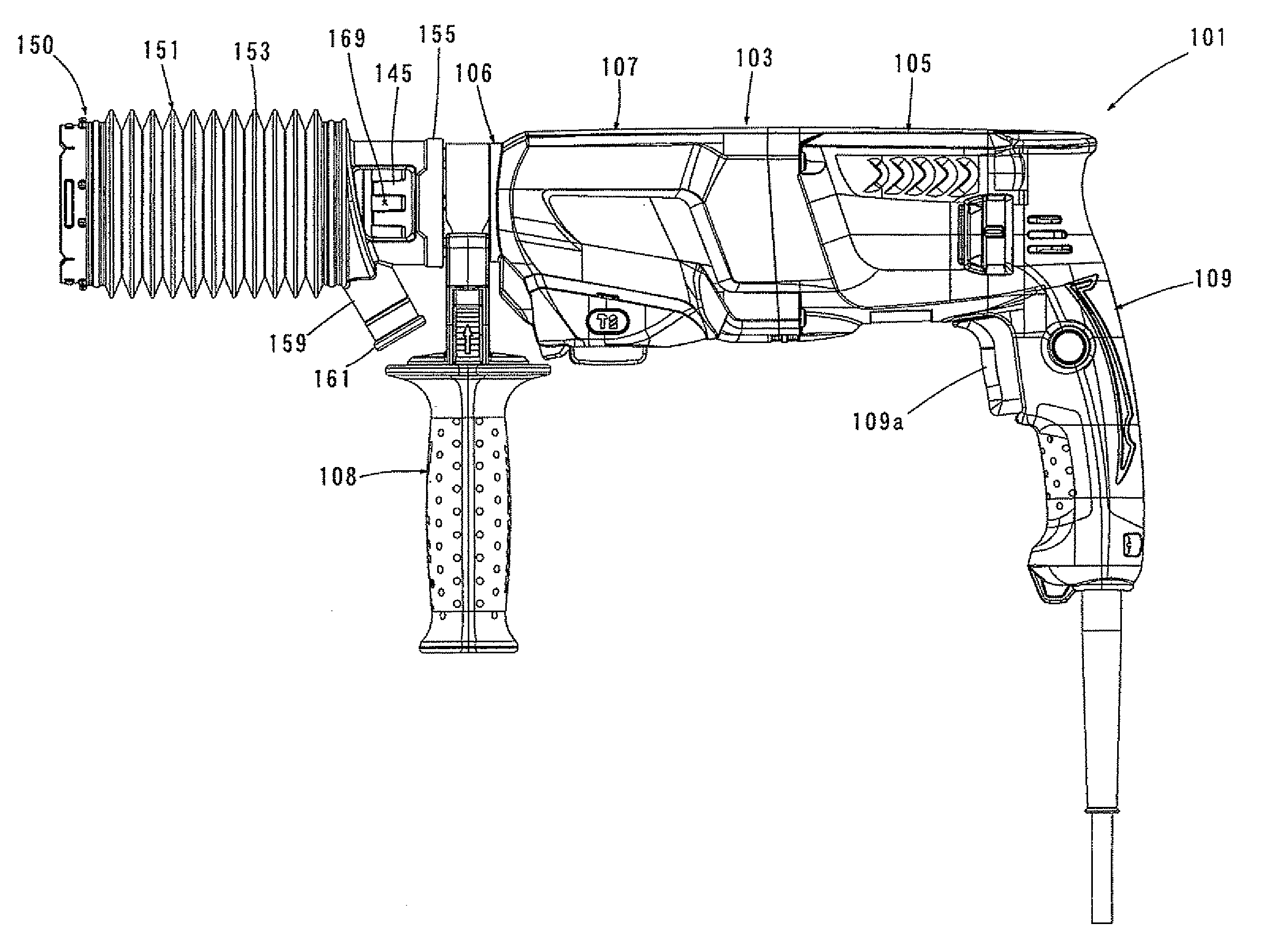
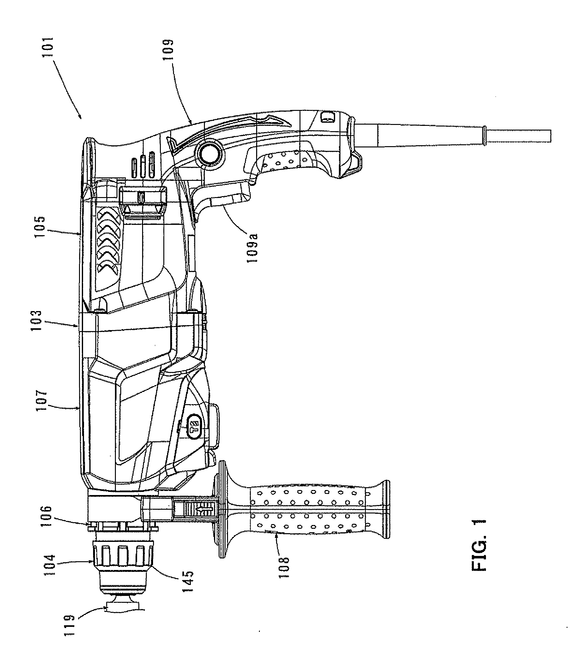
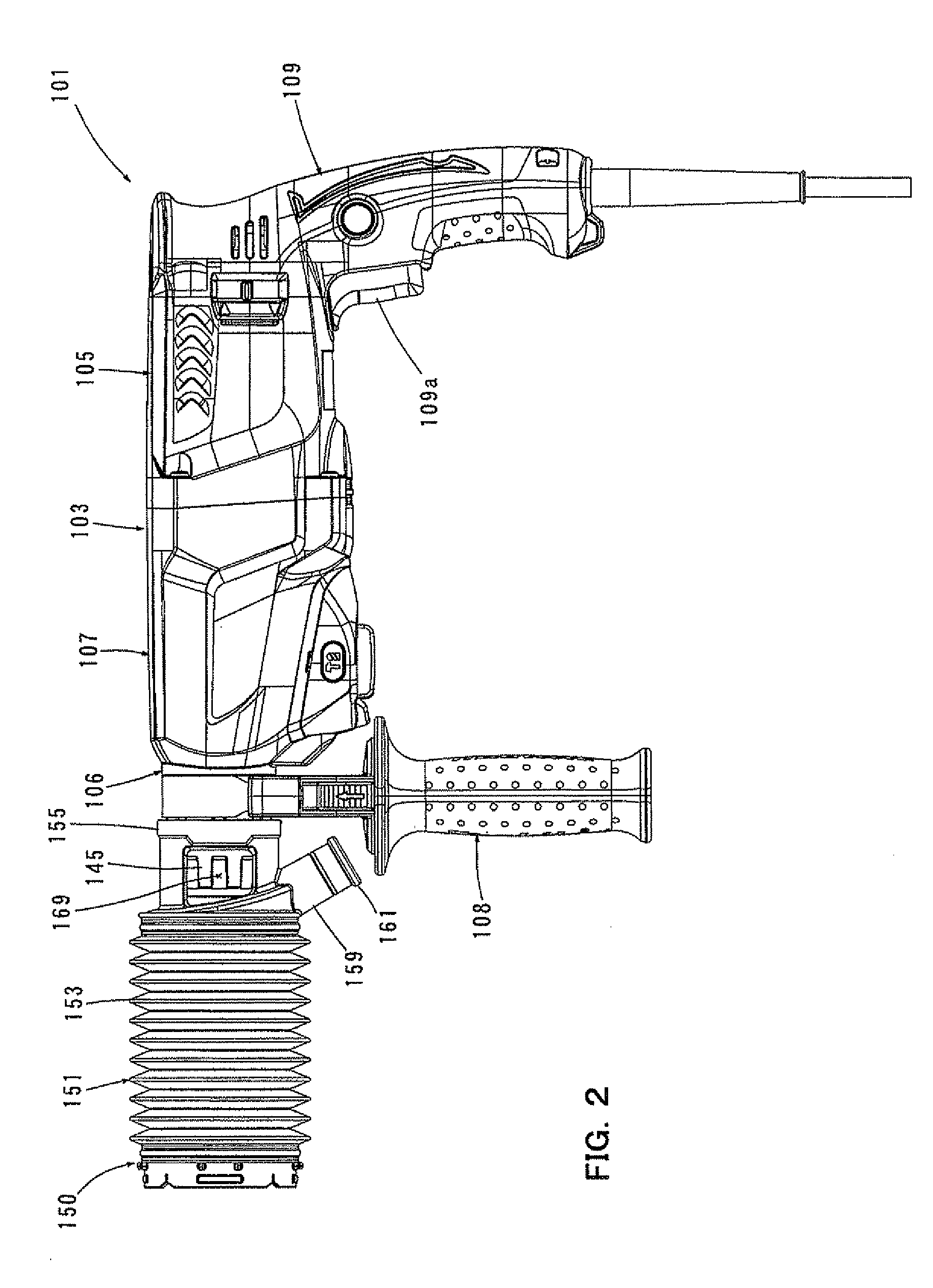
[0034]A first embodiment of the invention is now described with reference to FIGS. 1 to 7. In this embodiment, a dust collecting attachment is used on an electric hammer drill which is a representative example of a power tool. As shown in FIGS. 1 to 3, a hammer drill 101 according to this embodiment mainly includes a body 103 that forms an outer shell of the hammer drill 101, a hammer bit 119 detachably coupled to a tip end region (front end portion) of the body 103 via a tool holding device 104 and a handgrip 109 that is designed as a main handle and disposed on a rear end portion of the body 103 opposite from the hammer bit 119. The hammer bit 119 is held by the tool holding device 104 such that it is allowed to move with respect to the tool holding device 104 in its axial direction and prevented from rotating with respect to the tool holding device in its circumferential direction. The body 103 and the hammer bit 119 are features that correspond to the “tool body” and the “tool b...

second embodiment

[0056]A second embodiment of the invention is now explained in detail with reference to FIGS. 8 to 13. In this embodiment, a dust collecting attachment 250 is used on an electric hammer drill 201 of the type in which the rotation axis of the driving motor extends in a direction transverse to the axial direction of the hammer bit 219 (in the vertical direction). As shown in FIG. 8, the hammer drill 201 according to this embodiment mainly includes a body 203 that forms an outer shell of the hammer drill 201, a hammer bit 219 detachably coupled to a tip end region (front end portion) of the body 203 via a tool holding device 204 and a handgrip 209 that is designed as a main handle and disposed on a side (rear end portion) of the body 203 opposite from the hammer bit 219. The hammer bit 219 is held by the tool holding device 204 such that it is allowed to move with respect to the tool holding device 204 in its axial direction and prevented from rotating with respect to the tool holding ...

third embodiment

[0075]A third embodiment of the invention is now explained with reference to FIGS. 14 and 15. In this embodiment, a dust collecting attachment 350 is used on an electric hammer 301. Like the hammer drill 201 according to the second embodiment, the electric hammer 301 shown in FIG. 14 is of the type in which a driving motor 311 is vertically disposed such that its rotation axis extends in a direction transverse to an axial direction of a hammer bit 319. Further, the electric hammer 301 has a generally L-shaped body structure formed by a motor housing 305 and a gear housing 307. The electric hammer 301 has the same construction as the hammer drill 201 of the second embodiment except that an internal mechanism for driving the hammer bit 319 does not have a mechanism for transmitting rotation. Specifically, the internal mechanism of the electric hammer 301 includes a motion converting mechanism (crank mechanism) 313 that converts the rotating output of the driving motor 311 into linear ...


PUM

PropertyMeasurementUnit
cylindrical shapeaaaaaaaaaa
angleaaaaaaaaaa
workabilityaaaaaaaaaa

Abstract

A technique for allowing a user to operate an operating member disposed in a front end region of a power tool in the state in which a dust collecting attachment designed to be attached to the front end region of the power tool is left attached to the power tool. The dust collecting attachment is used on a power tool having an operating member for removal and / or bit angle setting of a tool bit coupled to a front end region of a tool body. The dust collecting attachment has a dust collecting member which can be attached to the front end region of the tool body. The dust collecting member has an opening formed in a region which faces the operating member in the state in which the dust collecting member is attached to the tool body, and the operating member can be operated by user's finger through the opening.

Description

BACKGROUND OF THE INVENTION[0001]1. Field of the Invention[0002]The invention relates to a dust collecting attachment for collecting dust generated during an operation of a power tool.[0003]2. Description of the Related Art[0004]Japanese patent publication No. 3726437 discloses a dust collecting attachment. This known dust collecting attachment is used on a hammer in which a hammer bit linearly moves in the axial direction and rotates in the circumferential direction of the tool bit. The known dust collecting attachment includes a dust collecting cup for collecting dust generated during drilling operation on concrete. The dust collecting cup has an extensible, cylindrical shape. The dust collecting cup is disposed in such a manner as to surround a front end region of the tool body around its longitudinal axis, and one end of the dust collecting cup in the longitudinal direction is detachably mounted to a side grip of the hammer drill.[0005]An operation sleeve for operating a bit mou...

Claims


Application Information

Patent Timeline
Patent Type & Authority Applications(United States)
IPC IPC(8): B23B47/00B25D17/14
CPCY10T408/50B23Q11/0046
Inventor YOSHIKANE, KIYONOBUMACHIDA, YOSHITAKAFURUSAWA, MASANORIKASUYA, YOSHIHIRO
Owner MAKITA CORP
Why Eureka
Try Eureka