Systems and methods for high efficiency regenerative selective catalytic reduction
Active Publication Date: 2011-01-13
BABCOCK POWER ENVIRONMENTAL INC (US)
View PDF26 Cites 5 Cited by
Summary
Abstract
Description
Claims
Application Information
AI Technical Summary
This helps you quickly interpret patents by identifying the three key elements:
Problems solved by technology
Method used
Benefits of technology
[0012]To achieve these and other advantages and in accordance with the purpose of the invention, as embodied herein, the invention includes a regenerative selective catalytic reduction process including providing a gas stream containing NOx to be treated. The process also includes introducing a reactant into the gas stream and directing the gas stream into contact with a catalyst to cause at least some of the NOx contained in the gas stream to be reduced. The gas stream is adapted to flow past the catalyst along the same flow direction throughou
Problems solved by technology
High-temperature combustion processes and other like technologies serve vital roles in industry; however, often an unfortunate by-product of such processes is the generation and release into the atmosphere of contaminants within outputted flue gas.
However, in view of the generally poor proven results of such techniques (i.e., NOx removal efficiencies of 50% or less), recent attention has focused instead upon various flue gas denitrification processes (i.e., processes for removing nitrogen from flue gas prior to the flue gas being released into the atmosphere).
Unfortunately, significant prob
Method used
Image
Click on the blue label to locate the original text in one second.
Reading with bidirectional positioning of images and text.
Examples
Example
[0027]Reference will now be made in detail to the present preferred embodiments of the invention, an example of which is illustrated in the accompanying drawings. The process and corresponding steps of the invention will be described in conjunction with the detailed description of the system.
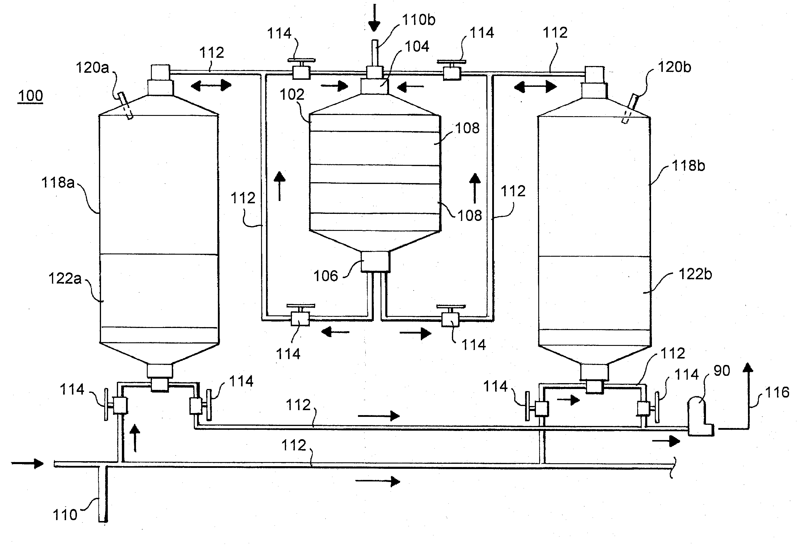
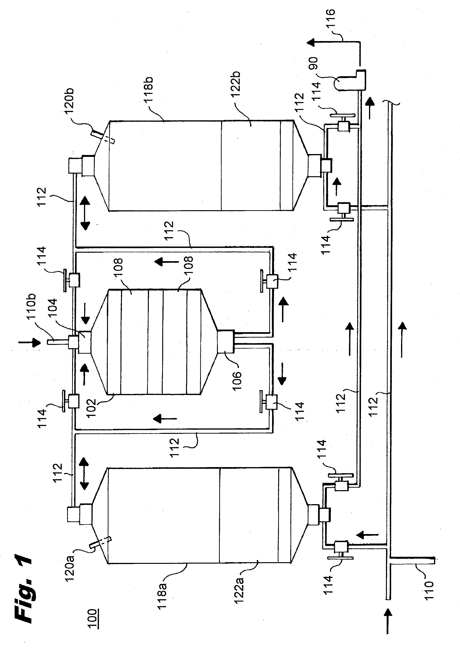
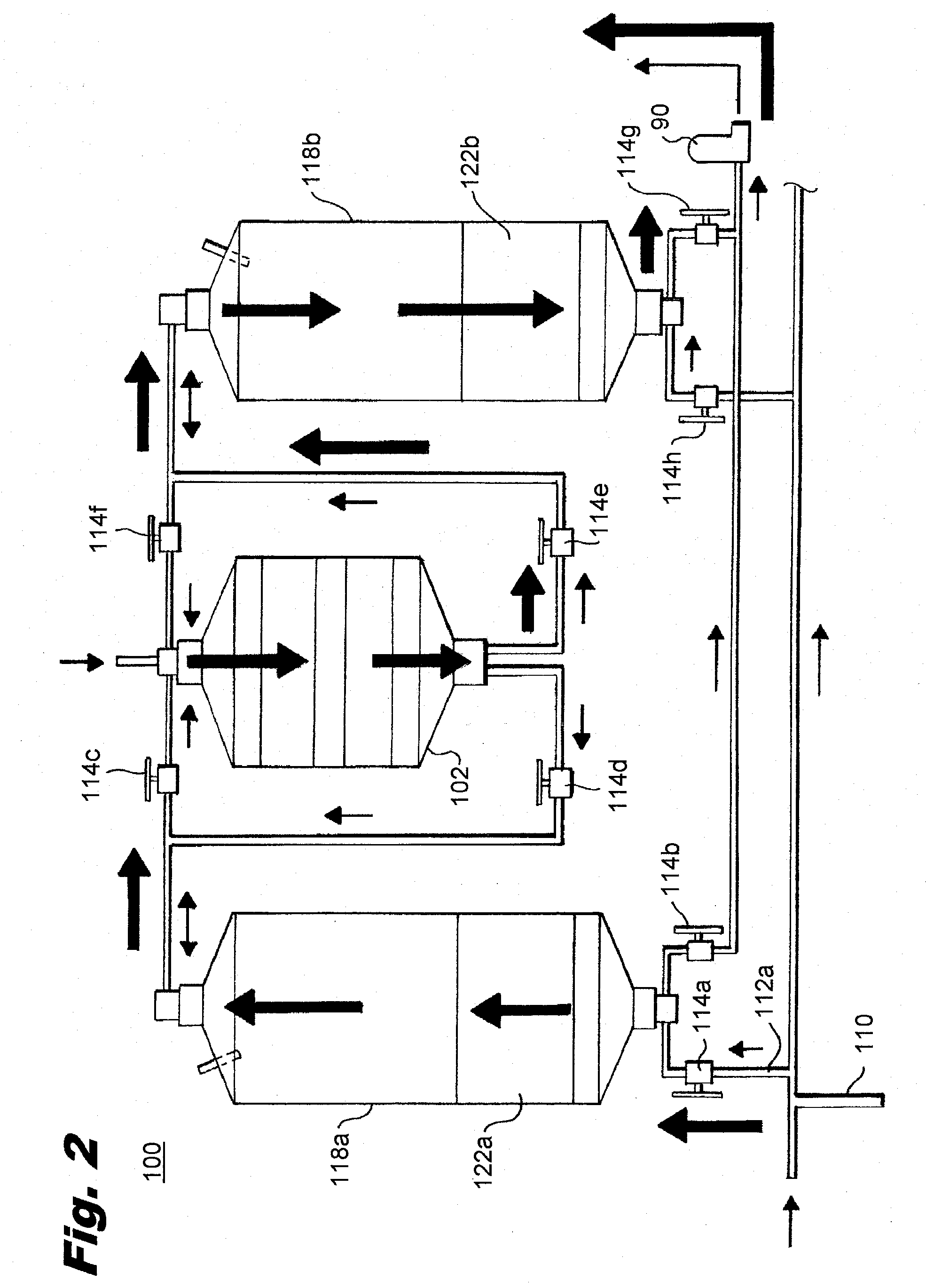
[0028]The devices and processes presented herein may be used for reducing NOx emissions in industrial and power generation plant equipment. Many of the concepts herein are explained further in U.S. Patent Application Pub. No. 2006 / 0067865, incorporated herein in its entirety. The present invention is particularly suited for reducing NOx out of flue gases prior to release into the atmosphere, in high-temperature combustion applications such as power plants, boilers, industrial machinery, and other similar equipment.
[0029]In accordance with the invention, a system for regenerative selective catalytic reduction is provided including a catalyst chamber having an inlet and an outlet, with a flow path...
PUM
Property
Measurement
Unit
Fraction
aaaaa
aaaaa
Fraction
aaaaa
aaaaa
Fraction
aaaaa
aaaaa
Abstract
The invention provides a system for regenerative selective catalytic reduction including a catalyst chamber that contains a catalyst for reducing NOx in a gas stream passing therethrough. The system also includes a reactant injector, first and second heat exchangers, and a valve manifold adapted to direct a substantially continuous gas stream through the heat exchangers and catalyst chamber in such a manner as to flow through the catalyst chamber in the same flow direction during each cycle of the system. The invention also provides a process of regenerative selective catalytic reduction wherein the gas stream through the catalyst chamber flows in the same flow direction during each cycle of the process.
Description
CROSS-REFERENCE TO RELATED APPLICATIONS[0001]This application is a continuation in part of U.S. application Ser. No. 12 / 355,231, filed Jan. 16, 2009, which in turn claims the benefit of U.S. Provisional Application No. 61 / 056,310, filed May 27, 2008. U.S. application Ser. No. 12 / 355,231 is a continuation in part of U.S. application Ser. No. 11 / 938,665, filed Nov. 12, 2007, now U.S. Pat. No. 7,494,625 and which in turn is a continuation of U.S. application Ser. No. 10 / 957,499, filed Sep. 30, 2004, now U.S. Pat. No. 7,294,321, each of which is incorporated by reference herein in its entirety.BACKGROUND OF THE INVENTION[0002]1. Field of the Invention[0003]The present invention relates to systems and methods for removing materials from flue gas, and, more particularly, to improved systems and methods for flue gas denitrification (i.e., for removing nitrogen oxides from flue gas) via regenerative selective catalytic reduction (RSCR).[0004]2. Description of Related Art[0005]High-temperatu...
Claims
Application Information
Patent Timeline
Application Date:The date an application was filed.
Publication Date:The date a patent or application was officially published.
First Publication Date:The earliest publication date of a patent with the same application number.
Issue Date:Publication date of the patent grant document.
PCT Entry Date:The Entry date of PCT National Phase.
Estimated Expiry Date:The statutory expiry date of a patent right according to the Patent Law, and it is the longest term of protection that the patent right can achieve without the termination of the patent right due to other reasons(Term extension factor has been taken into account ).
Invalid Date:Actual expiry date is based on effective date or publication date of legal transaction data of invalid patent.