USB a-type socket

a usb a-type socket and socket technology, applied in the field of electronic connectors, can solve the problems of affecting affecting the electrical properties of the device, and affecting the operation of the device, so as to ensure the positional stability of the first terminal and improve the reliability of the usb a-type sock

Inactive Publication Date: 2011-01-13
COMPUPACK TECH
View PDF2 Cites 11 Cited by
  • Summary
  • Abstract
  • Description
  • Claims
  • Application Information

AI Technical Summary

Benefits of technology

[0013]Therefore, one objective of the present invention is to provide a USB A-type socket which complies with the USB 3.0 specification and in which first terminals complying with the Super Speed USB 3.0 specification and an insulating body are integrated as a composite member so that the insulating body partially wraps and firmly holds the first terminals. Consequently, positional stability of the first terminals is increased so as to ensure excellent electronic property and reliability of the disclosed USB A-type socket.
[0018]Therefore, the USB A-type socket of the present invention has the first terminals and the insulating body integrated as the one-piece composite member so that the insulating body firmly holds the first terminals and thereby ensures positional stability of the first terminals. Consequently, the USB A-type socket conforms to design specifications and provides the desired electronic properties, thus improving the reliability of the USB A-type socket.

Problems solved by technology

However, this assembling process may sometimes result in askew positioned terminals.
Particularly, after the USB technology stepped into the era of the 3.0 Version, the number of terminals in a USB A-type socket has increased to nine, which increases the risk of defective assembly.
An ill-performed assembling process not only causes the actual dimensions of terminals to deviate from design, but also brings adverse effects to the electrical properties, and thus lowers the reliability, of finished products so that consumers' rights are compromised.

Method used


Image

  • USB a-type socket
  • USB a-type socket
  • USB a-type socket

Examples


Embodiment Construction

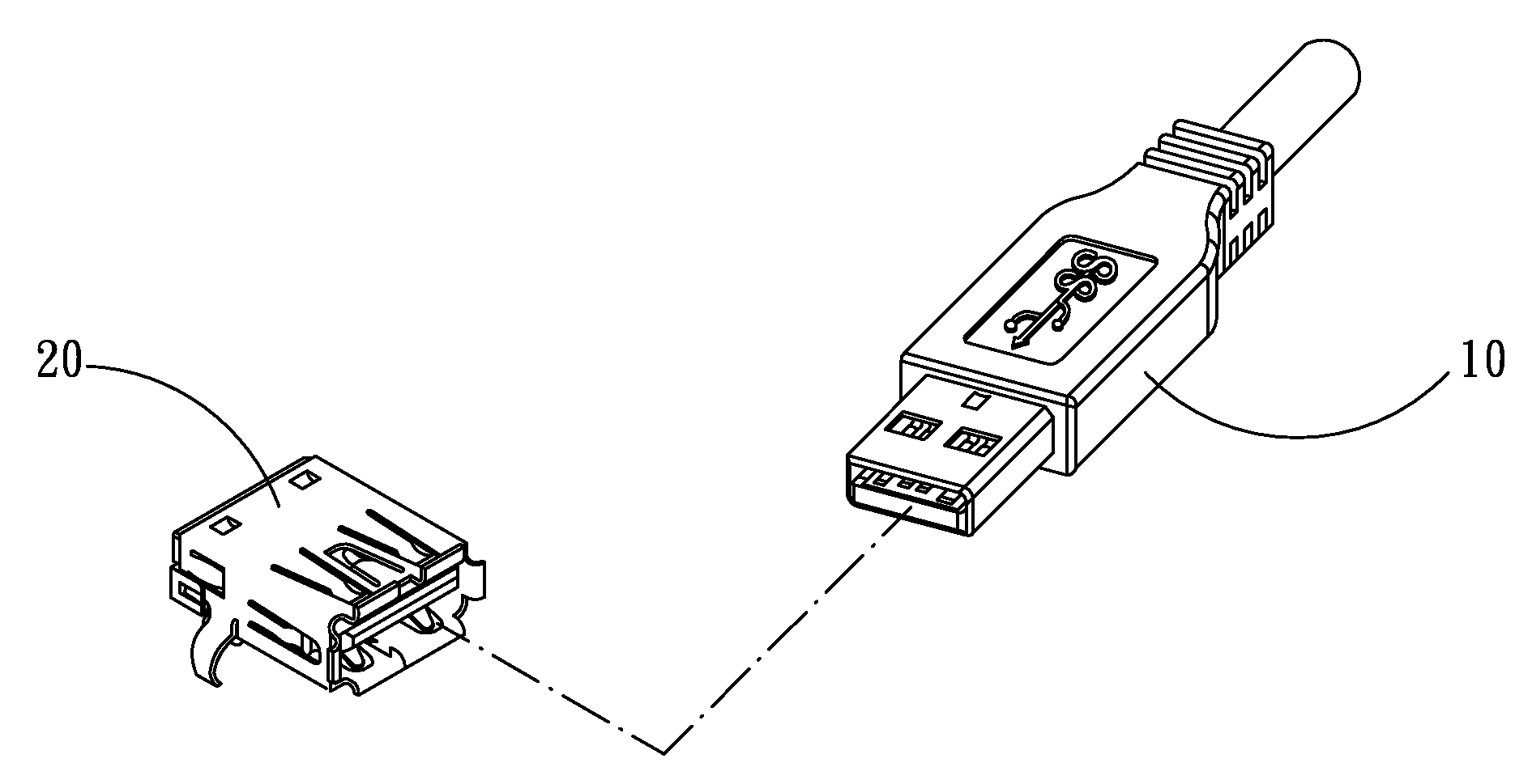
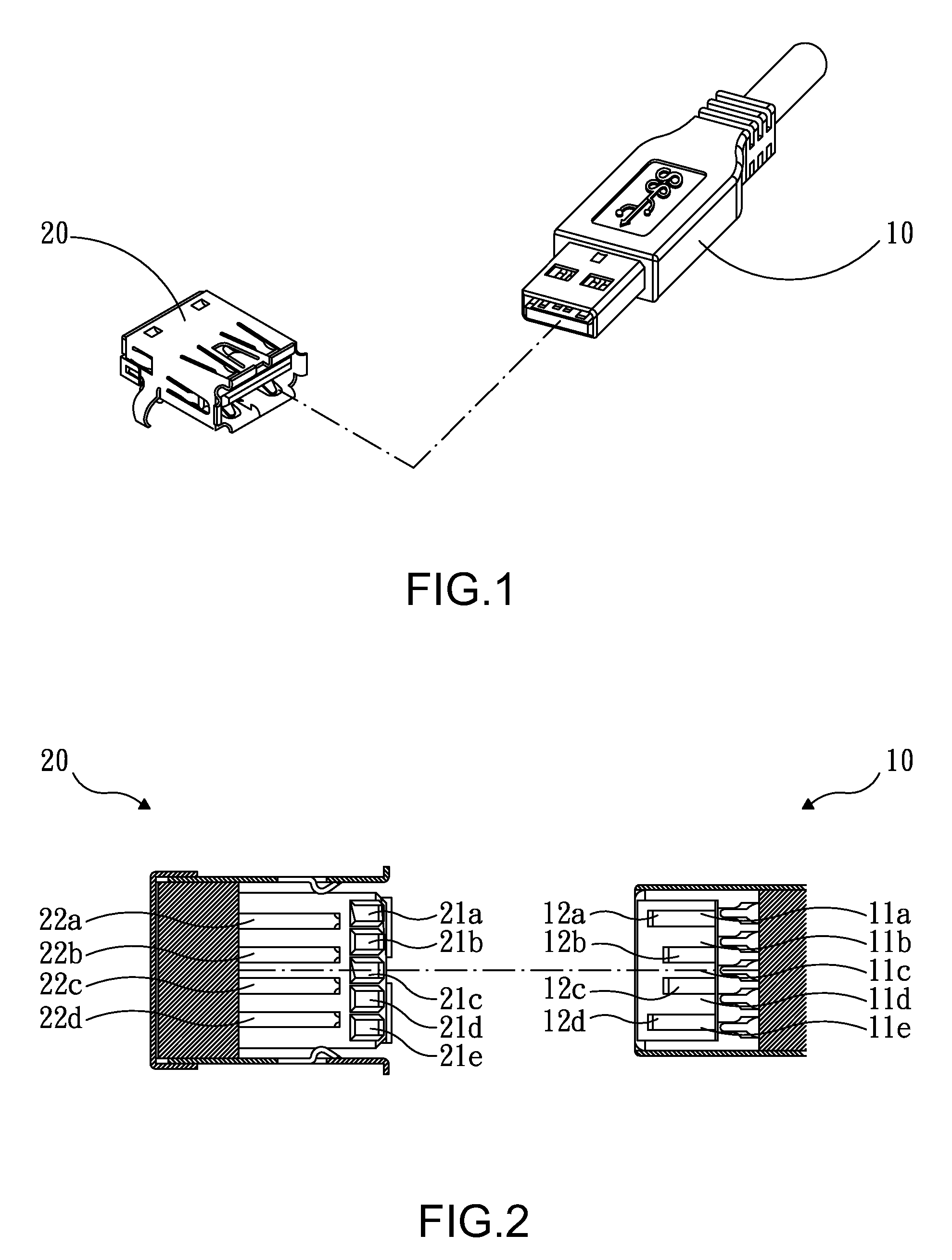
[0025]The present invention provides a USB A-type socket that complies with the USB 3.0 specification and is configured for coupling with a standard USB 3.0 A-type plug.

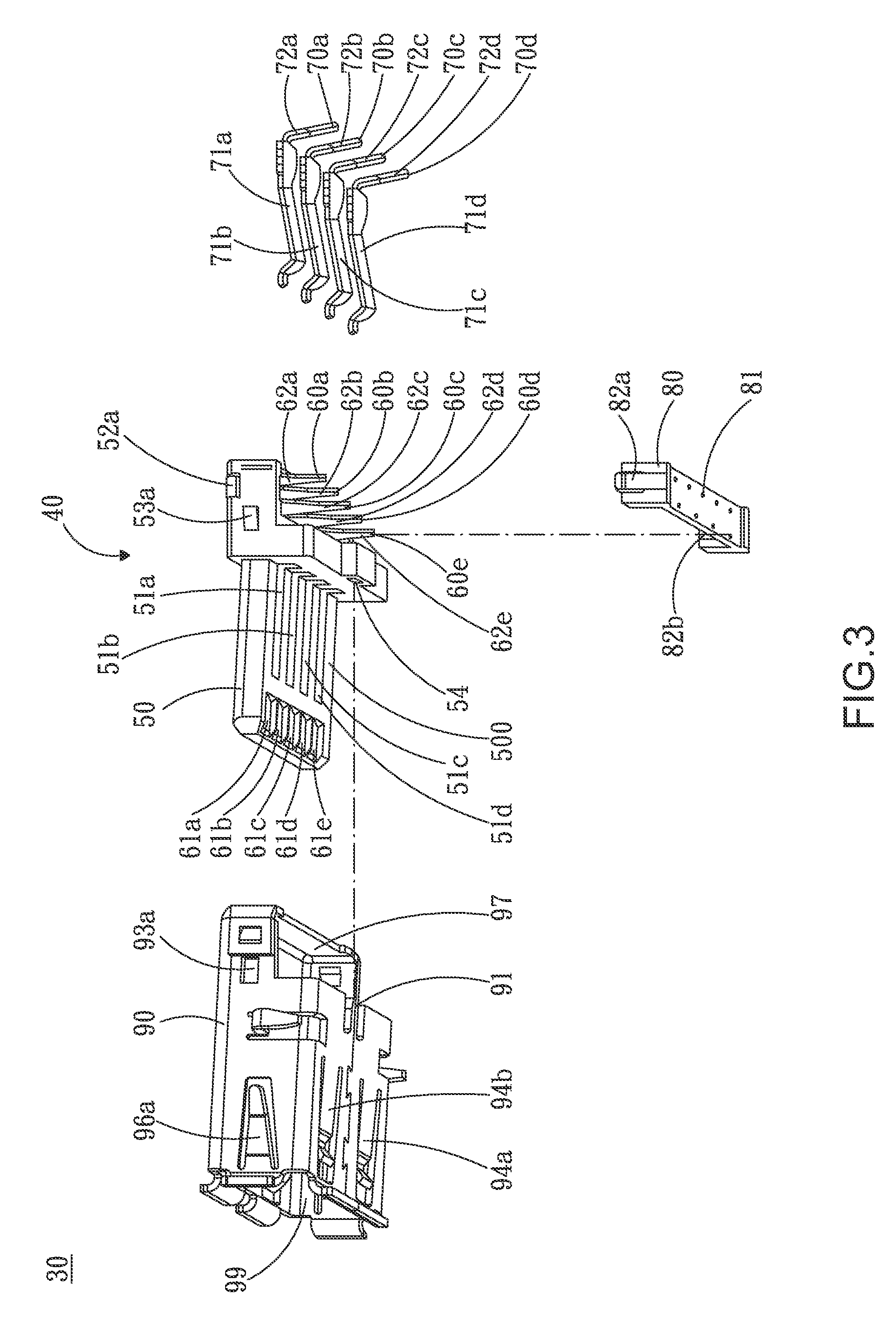
[0026]Please refer to FIGS. 3 through 7 for an embodiment of the present invention, wherein FIG. 3 is an exploded perspective view of the USB A-type socket of the present invention, FIG. 4 is another exploded perspective view of the USB A-type socket of the present invention, and FIGS. 5 through 7 are perspective views of the USB A-type socket of the present invention taken from different viewing angles.

[0027]As shown in the drawings, the USB A-type socket 30 primarily comprises a composite member 40, four electrically conductive second terminals 70a through 70d, a seat 80, and a metal housing 90. The composite member 40 includes five electrically conductive first terminals 60a through 60e and an insulating body 50. The insulating body 50 partially wraps and firmly holds the first terminals 60a through 60e. In the de...


PUM


Abstract

A USB (Universal Serial Bus) A-type socket configured for coupling with a USB A-type plug complies with the USB 3.0 specification and includes a composite member, a plurality of second terminals, and a metal housing. The composite member includes a plurality of first terminals and an insulating body, wherein the insulating body partially wraps and firmly holds the first terminals. The second terminals are assembled to guiding rails provided on the composite member. The metal housing encloses the composite member. Since the first terminals and the insulating body are integrated as the one-piece composite member, positional stability of the first terminals is ensured.

Description

BACKGROUND OF THE INVENTION[0001]1. Technical Field[0002]The present invention relates to electronic connectors and, more particularly, to a standard USB (Universal Serial Bus) A-type socket that complies with the USB 3.0 specification.[0003]2. Description of Related Art[0004]The USB interface is the most popular transmission interface for IT products nowadays. For example, USB compatible connectors are extensively used in various peripherals for computers and digital audio-video devices, such as mice, keyboards, memory sticks, card readers, and so on, for convenient and rapid data transmission.[0005]Since the introduction of USB Specification Version 1.0 in 1996, the USB-related technology has progressed considerably so that the USB 3.0 Specification was published in 2008, providing a transmission rate up to 4.8 Gbps. Structurally speaking, both USB 1.x and USB 2.0 use four contacts, namely a pair of power cords and a pair of differential signaling lines, for half-duplex transmissi...

Claims


Application Information

Patent Timeline
Patent Type & Authority Applications(United States)
IPC IPC(8): H01R24/00
CPCH01R24/60H01R27/00
Inventor WANG, JUNG JUI
Owner COMPUPACK TECH
Why Eureka
Try Eureka