Artificial exoskeleton device or an orthotic device comprising an integrated hinge structure

a technology of hinge structure and exoskeleton, which is applied in the field of artificial exoskeleton devices and/or machines, can solve the problems of structurally limited range of motion if needed, and achieve the effect of improving the hinge structur

Inactive Publication Date: 2011-01-13
MATERIALISE NV
View PDF11 Cites 30 Cited by
  • Summary
  • Abstract
  • Description
  • Claims
  • Application Information

AI Technical Summary

Benefits of technology

[0016]An object of the present invention is to provide an exoskeletal device, e.g. orthotic devices and, more specifically, exoskeletal devices, e.g. orthotic devices having a better hinge structure.
[0018]In one aspect, the present invention provides an exoskeletal, e.g. orthotic device comprising at least one integrated pivot or hinge structure with a specified axis of rotation, such as one coinciding or approximating with the natural rotation axis of the ankle, knee, elbow or any relevant joint. Preferably the pivot or hinged structure is provided with a personalised resistance to rotation, e.g. a rotation controller. The pivot or hinge structure is a pivot or hinge comprising at least two separate cylindrical parts that rotate with respect to each other, the axis of rotation being at the centre of the cylinder. The pivot or hinge can be placed to the optimal location and orientation in regard to the limb or anatomical features observed or measured from the patient thanks to the layered manufacturing technique. The range of motion can be structurally limited if needed, e.g. by a limiter. This enables more possibilities for adjustment when the exoskeletal device, e.g. orthotic device is fitted to the patient to ensure a better fit and functionality.
[0020]A rotation controller to provide a resistance to rotation can be achieved by connecting the upper and lower halves with elastically or plastically deformable structures such as spiral and / or coil springs. The main hinge structure carries the majority of the vertical loads together with the patients limb—in an orthotic application—and prevents unnecessary motion and the deforming structures provide the required resistance to motion. Furthermore, in this invention the hinge and the adjustment structures are built as one part, as enabled by layer manufacturing, and as such offer several advantages over traditional manufacturing. Furthermore, the hinge structure in this invention does not have to lay flat on a plane, but can be contoured along a round, flat or elongated sphere or any combination of these shapes. This is beneficial as the centre of rotation of the hinge can be placed very close to the ankle of the patient. The closer the hinge is to the joint, the more natural the motion will be. Also, these possibilities will enable the appearance of the orthoses to be different allowing for more possibilities for product design and personalization.
[0022]The present invention provides the advantage that the hinge structure can be optimally adapted in its shape to various parts of the body such as the ankle or the elbow for which a dished shaped hinge structure is preferred, i.e. fits more closely and can be more comfortable. This allows a close fitting exoskeletal device. It also allows a device that can be adapted to the patient or wearer of the orthosis.
[0023]Preferably, means for limiting the angular rotational movement of the first part with respect to the second part can be provided. This limiter allows restraint of the rotation when this is medically advantageous. Preferably, the means for limiting is formed integrally with the pivot structure by the layered manufacturing, e.g. rapid prototyping technique. This provides a convenient way of building in the restraint without requiring extra steps.

Problems solved by technology

The range of motion can be structurally limited if needed, e.g. by a limiter.

Method used


Image

  • Artificial exoskeleton device or an orthotic device comprising an integrated hinge structure
  • Artificial exoskeleton device or an orthotic device comprising an integrated hinge structure
  • Artificial exoskeleton device or an orthotic device comprising an integrated hinge structure

Examples


Embodiment Construction

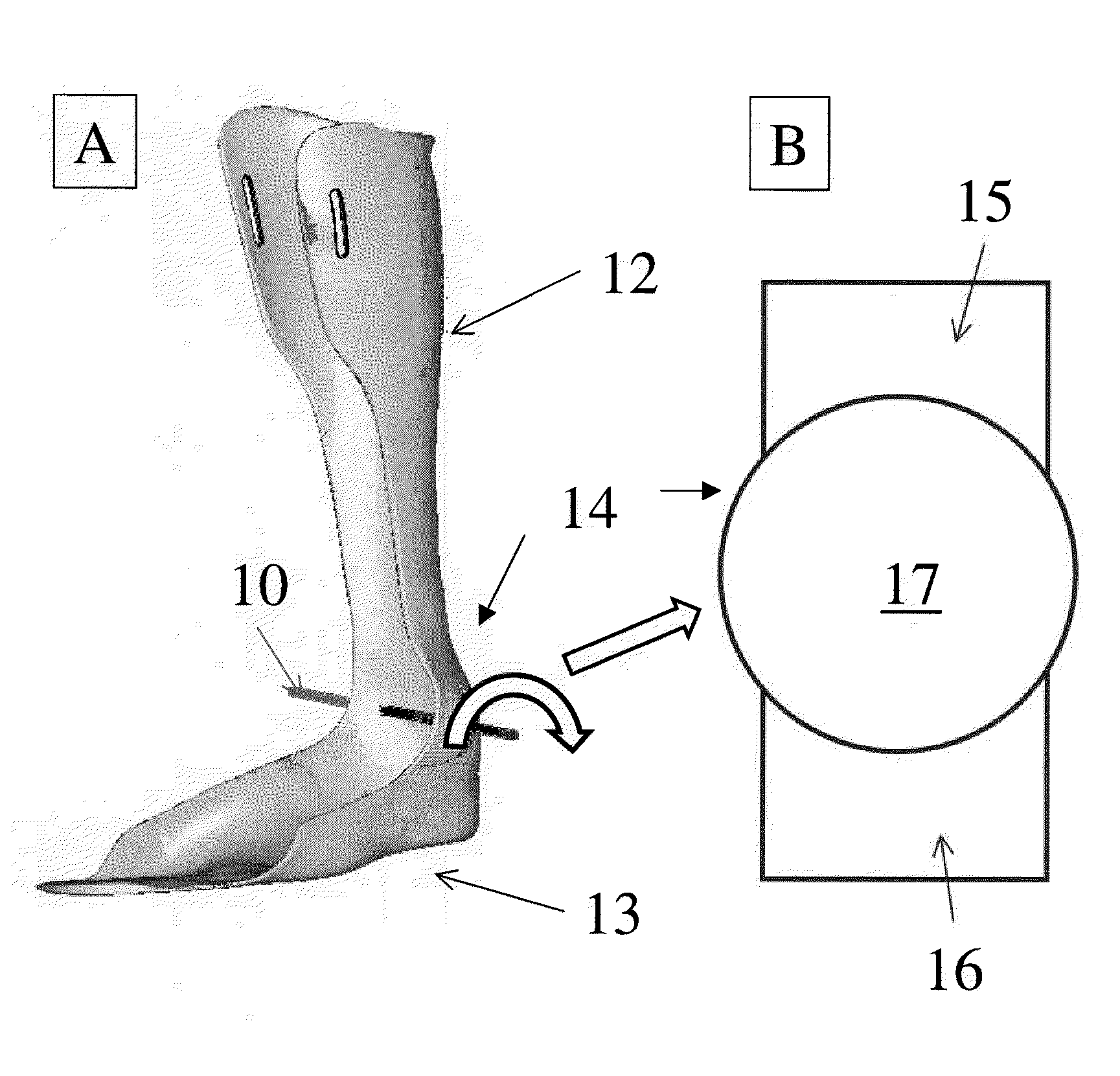
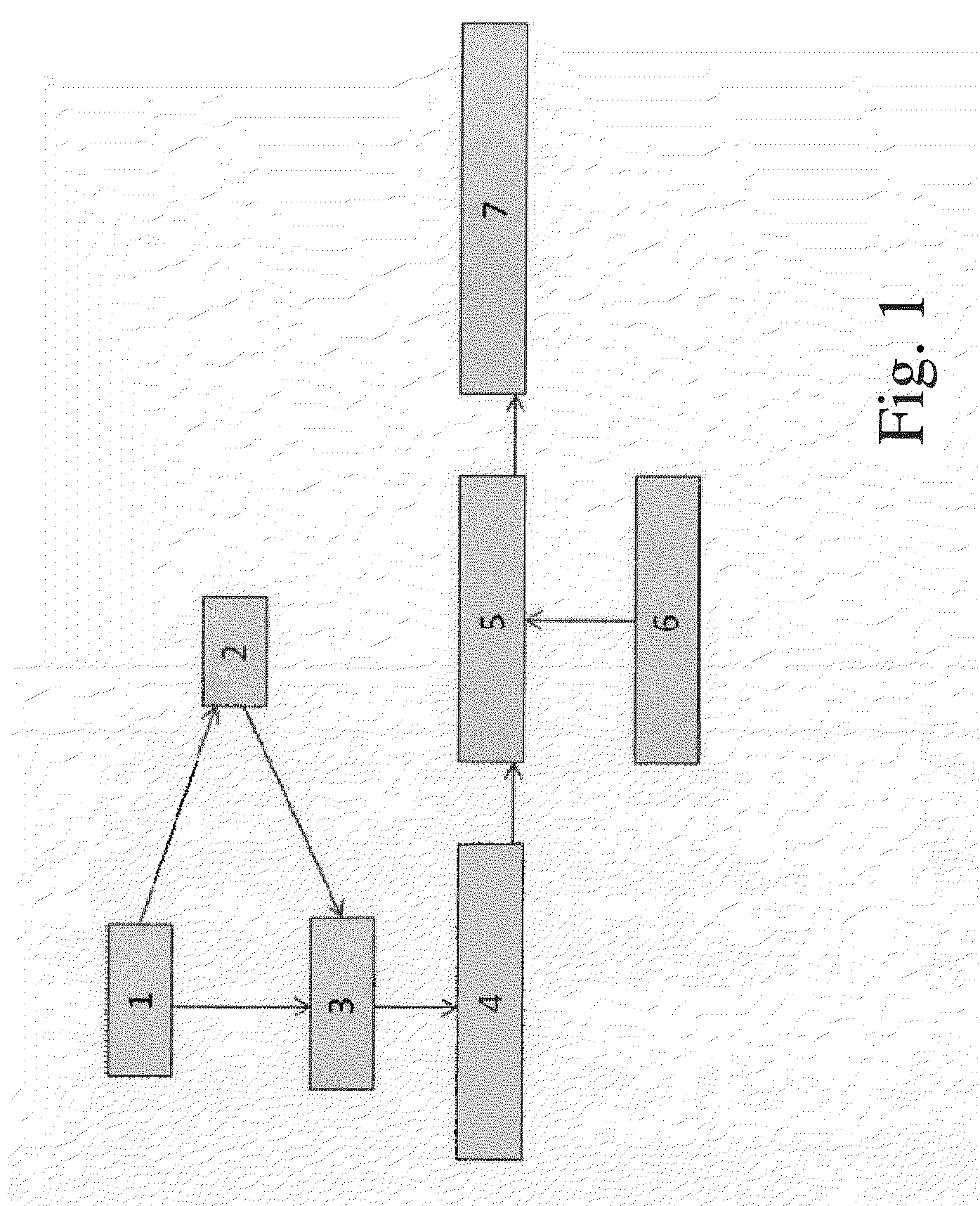
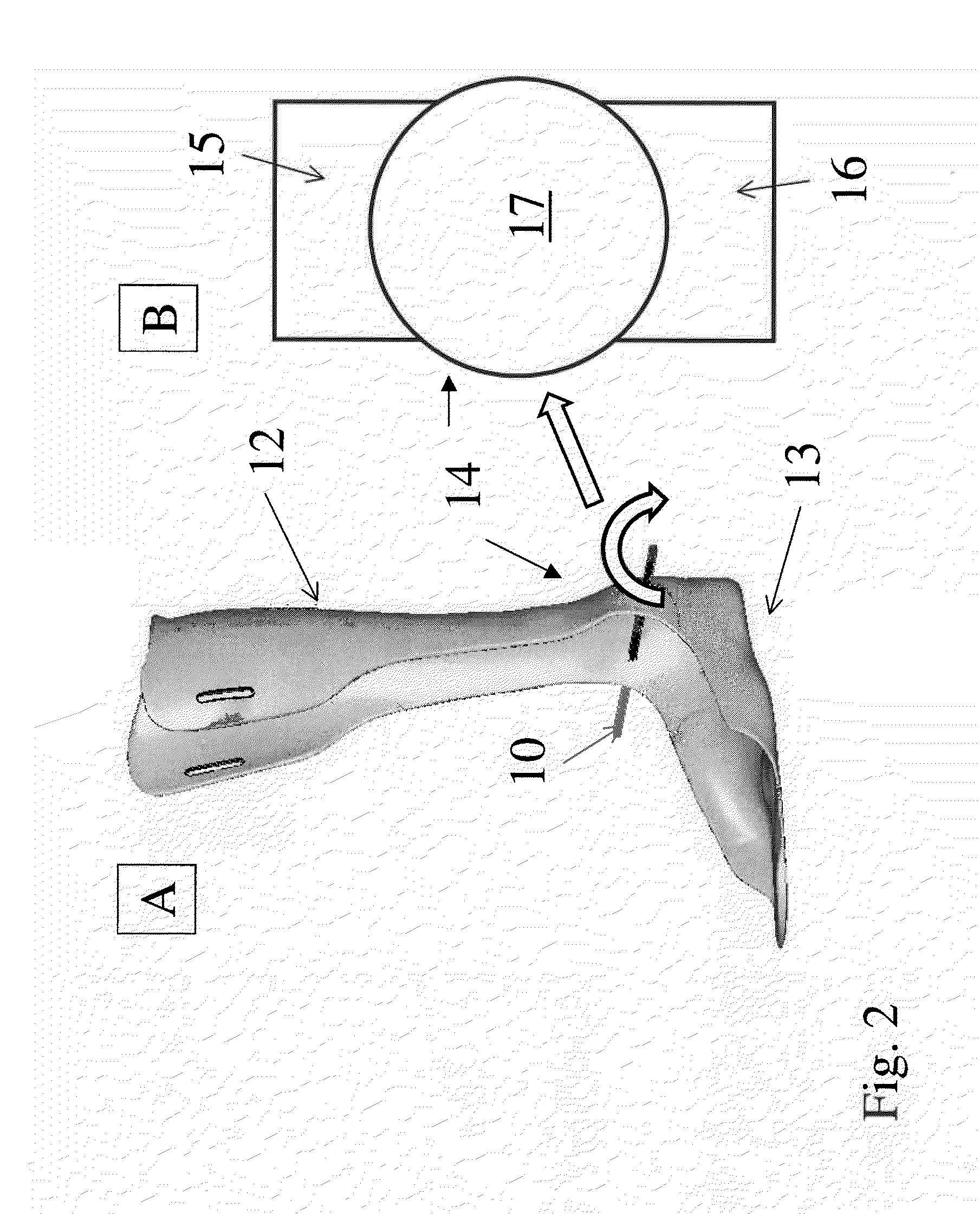
[0047]In the following detailed description of the preferred embodiments, reference is made to the accompanying drawings, which form a part hereof, and within which are shown by way of illustration specific embodiments by which the invention may be practiced. The drawings described are only schematic and are non-limiting. In the drawings, the size of some of the elements may be exaggerated and not drawn on scale for illustrative purposes. Those skilled in the art will recognize that other embodiments may be utilized and structural changes may be made without departing from the scope of the invention.

[0048]Furthermore, the terms first, second, third and the like in the description and in the claims, are used for distinguishing between similar elements and not necessarily for describing a sequential or chronological order. It is to be understood that the terms so used are interchangeable under appropriate circumstances and that the embodiments of the invention described herein are cap...


PUM

PropertyMeasurementUnit
angular rotational movementaaaaaaaaaa
resilient forceaaaaaaaaaa
rotationaaaaaaaaaa

Abstract

A pivot or hinge structure integrated into the main body of an exoskeletal, e.g. orthotic device is described as well as methods for computer aided designing and making of these devices. Computer systems and software for carrying out the methods are also described.The integrated pivot or hinge structure has a specified axis of rotation, such as one coinciding or approximating with the natural rotation axis of the ankle, knee, elbow or any other relevant joint. Preferably the pivot or hinged structure is provided with a personalised resistance to rotation. The pivot or hinge structure is a pivot or hinge comprising at least two separate cylindrical parts that rotate with respect to each other, the axis of rotation being at the centre of the cylinder. The pivot or hinge can be placed to the optimal location and orientation in regard to the limb or anatomical features observed or measured from the patient thanks to the layered manufacturing technique. The range of motion can be structurally limited if needed. This enables more possibilities for adjustment when the exoskeletal device, e.g. orthotic device is fitted to the patient to ensure a better fit and functionality.

Description

CROSS-REFERENCE TO RELATED APPLICATIONS[0001]This application claims benefit of GB 0911953.8, filed Jul. 9, 2009, which is hereby incorporated by reference.FIELD OF THE INVENTION[0002]The present invention relates generally to the field of artificial exoskeletal devices and / or machines, such as orthotic devices and, more specifically, to artificial exoskeletal devices and / or machines, such as orthotic devices having a hinge structure integrated into the main body of the artificial exoskeleton device and / or machines, or orthosis as well as methods for computer aided designing and making of these devices. The present invention also relates to computer systems and software for carrying out the methodsBACKGROUND TO THE INVENTION[0003]All documents referred to herein, or the indicated portions, are hereby incorporated by reference. No document, however, is admitted to be prior art to the claimed subject matter.[0004]An artificial exoskeleton device is a device that mimics functionally at...

Claims


Application Information

Patent Timeline
Patent Type & Authority Applications(United States)
IPC IPC(8): A61F5/00B23P11/00
CPCA61F5/0102Y10T29/49826B29C67/0051A61F5/0127
Inventor PALLARI, JARI HEIKKI PETTERIJENS, ROEL WIRIX-SPEET
Owner MATERIALISE NV
Why Eureka
Try Eureka