Negative Pressure Bandage

a bandage and pressure technology, applied in the field of negative pressure bandage, can solve the problems of poor wound resistance, interference of blood flow in the damaged blood vessels, and interruption of wound repair

Active Publication Date: 2011-01-13
NAT PINGTUNG UNIV OF SCI & TECH
View PDF6 Cites 9 Cited by
  • Summary
  • Abstract
  • Description
  • Claims
  • Application Information

AI Technical Summary

Benefits of technology

[0008]An objective of the present invention is to provide a negative pre...

Problems solved by technology

However, in the inflammatory phase, the blood flow in the damaged blood vessels may be interfered by the clotting taking place in the capillaries.
On the other hand, the wound repairment may also be interrupted due to the tissue timidity caused by serious infection of wound.
As a result, the lack of oxygen and nutrition in the epithelium cells and subcutaneous tissue around...

Method used


Image

  • Negative Pressure Bandage
  • Negative Pressure Bandage
  • Negative Pressure Bandage

Examples


Embodiment Construction

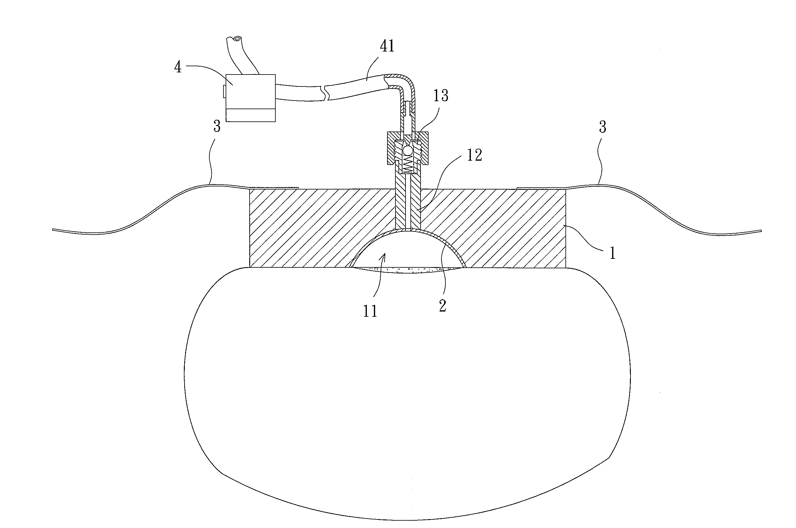
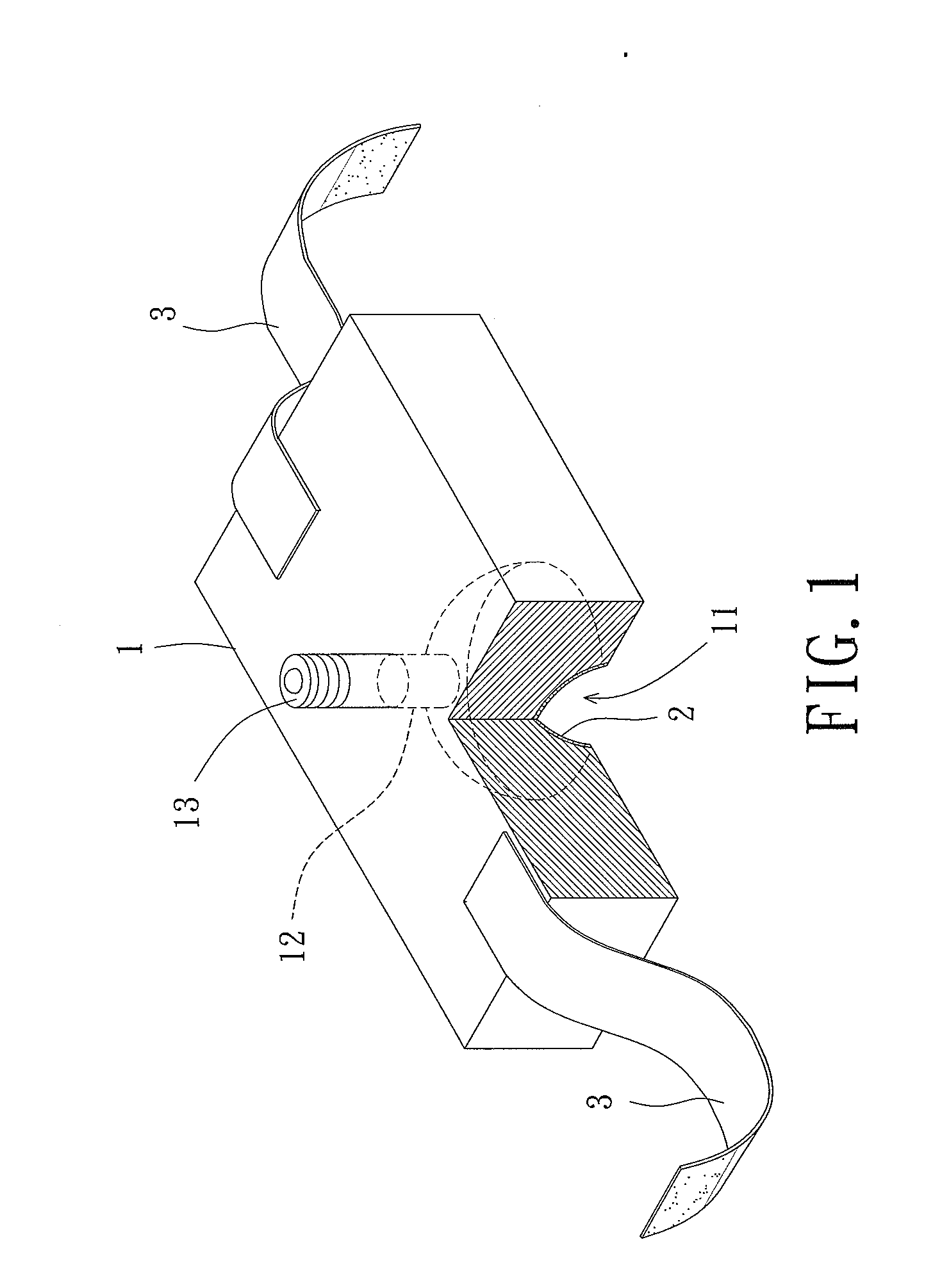
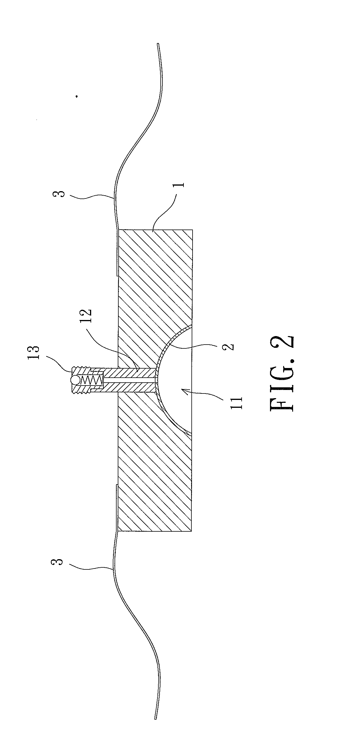
[0023]Referring to FIGS. 1 and 2, a negative pressure bandage is disclosed according to a first embodiment of the invention. The negative pressure bandage comprises a banding portion 1, at least one infiltration 2 covered on the banding portion 1, and at least one fixing member 3 adapted to fix the banding portion 1 on a treatment part 92 of a body portion 94 of a user requiring negative pressure treatment.

[0024]In the preferred form shown, the banding portion 1 is made of shapeable sponge, elastic bandage, or the like. The banding portion 1 can be of any desired shape and size. The banding portion 1 includes at least one recession 11, a tube 12 and a check valve 13. The recession 11 is formed in one side of the banding portion 1 and faces the treatment part 92 of the user. The recession 11 can be of any shape and size corresponding to the shape and size of the treatment part 92. The tube 12 is embedded in the banding portion 1. The tube 12 has a first end 121 connected with the at ...


PUM


Abstract

A pressure bandage comprises a banding porting, at least one infiltration and at least one fixing member. The banding portion includes at least one recession formed in one side of the banding portion, at least one tube having a first and a second ends, and at least one check valve mounted in the second end of the tube. The first end of the tube is connected to the recession. The infiltration is coupled on the inner surface of the recession of the banding portion. The fixing member fixes the banding portion to a treatment part.

Description

BACKGROUND OF THE INVENTION[0001]1. Field of the Invention[0002]The present invention generally relates to a negative pressure bandage and, more particularly, to a negative pressure bandage that allows free movement of the user using the negative pressure bandage.[0003]2. Description of the Related Art[0004]As known by the technician who is familiar with vacuum sealing therapy, wound healing is a process of self-repairment of skin after trauma, which may be categorized into hemostasis, inflammatory, proliferative and remodeling phases. In the inflammatory phase, some bacteria are cleaned and removed leading to the migration and division of epithelium or subcutaneous tissues involved in. As a result, the blood flow may increase in order to bring about a significant amount of releasing factors for initiating the proliferation of cells. However, in the inflammatory phase, the blood flow in the damaged blood vessels may be interfered by the clotting taking place in the capillaries. In t...

Claims


Application Information

Patent Timeline
IPC IPC(8): A61M1/00
CPCA61F13/00068A61F2013/00119A61F2013/00174A61M1/0086A61F2013/00536A61F2013/0054A61M1/0088A61F2013/00412A61M1/915A61M1/913A61M1/918A61M1/96A61M1/74
Inventor LU, WEI-HUACHEN, YUNG-CHUANCHIANG, TING-LUNG
Owner NAT PINGTUNG UNIV OF SCI & TECH
Why Eureka
Try Eureka